Wiring

All posts tagged Wiring

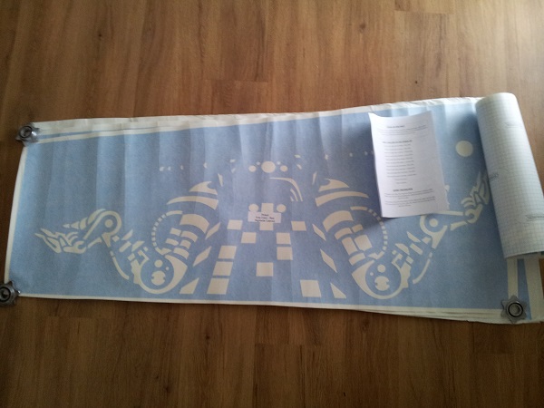
This update took much longer than I expected it would, but finally the headbox has been patched and repainted. Outside of some cosmetic damage, the headbox is in good condition. While the artwork was faded in parts and there was some minor damage to the wood, it was at least strong and stable. Unlike the Fireball Classic I recently restored, the Pinbot cabinet artwork is painted on with the use of stencils. A full set are available at TwistedPins and Santa managed to deliver a set to me during the Xmas period and it was time to put them to use.

I’m going to break the process up into two parts. Firstly i’ll do the headbox, which will then be followed by the cabinet. To begin with, I removed the stencils from the packaging and flattened them out. There are two stencils per side – one for the red/orange colour and the second for the yellow. It also comes with a set of instructions which are not complicated – just common sense really.

Pinbot pinball
Continue Reading

The coin door on my Pinbot machine is in need of some attention. It’s not the worst I’ve seen (actually, far from it), but it could certainly do with some love. The photo makes it look a bit better than it really is. Up close, there are far more chips and scratches along the edges of both the coin accept and coin return face plates. On the up side, the door itself is solid and should do up nicely.

The middle and right coin accept slots have been covered up with tape (there are no coin mechs hooked up to either of these).

Pinbot coin door start
Continue Reading

After playing my Nugent a lot over the last two weeks, I decided it was time to make some improvements to the gameplay – this means giving some attention to the playfield. For now, I’m keeping it simple but in the long run I plan to use some Novus 2 and wax along with leveling the inserts to really improvement playfield.

First step was to get access to the playfield. To do this, I need to remove the lockdown bar which side across the end of the pinball table. Just inside the coin door – at the top right – is a handle. Pulling this to the left unlocks the lockdown bar.

Stern lockdown bar
Continue Reading

When I first opened the back of the machine, this is the sight I was greeted with:

Blocked

A number of things bothered me:
1) The bottom left corner of the game board was physically resting on top of the switcher. This has actually left some marks across the top of the switcher and some discolouration on the side of the pcb.
2) The middle of the PCB is physically resting on top of the fuse switch. Not a big deal but I don’t like the fact the PCB is actually resting on components of the machine.
3) The pcb isn’t sitting properly due to a makeshift foot (see the top right pcb foot), which leaves it on an angle.
4) Loose power cable hanging across the PCB
5) The frame holding the PCB in place is attached to the base of the monitor panel. While the pcb itself doesn’t have much weight (and any it does have is currently resting on the switcher) I want to reposition it so it’s away from the monitor and not in the way of everything. There is no way to access the speakers, coin mech or steering wheel with this set up.
Continue Reading

Locating information specific to the Namco Pole Position 2 pin outs proved to be a challenge. The Atari pin outs are easy enough to find and are documented on a number of sites (although a number of sites reference the same documentation). The Atari PCB uses a 30 pin connector on the video board and a 44 pin connector on the CPU board. The Namco board set however uses a 20 pin connector on its video board and a 36 pin connector on the CPU board.

After much Googling, I came across a YouTube video showing the exact Namco PCB I owned. Interested, I took a look and read the comments. Tucked away in the comments was a link to a Japanese website that supposedly contained the pin outs for the Nambo Pole Position board set. Returning to Google with the web address, I was able to view a translated version. I was happy to see that this was the actual pin out for the Namco board set!

I’ve reproduced the pin out diagram here:

– CPU Board (J4): 36 Pin

Component side Solder Side
+12V OUT A 1 +12V OUT
LOCK OUT B 2 START LAMP
COIN COUNTER 1 C 3 COIN COUNTER 2
SERVICE D 4 TEST
COIN 1 E 5 COIN 2
START 1 F 6 START 2
N/A H 7 SHIFTER
GND J 8 GND
SOUND 1 K 9 SOUND 2
SOUND 3 L 10 SOUND 4
SOUND GND M 11 SOUND GND
VOL GND N 12 VOL GND
GAS P 13 BRAKE
VOL VCC R 14 VOL VCC
+5V OUT S 15 +5V OUT
N/A T 16 N/A
STEERING 1 U 17 STEERING 2
GND V 18 GND

* connect the “START 1” and “START 0”

– Video Board (J1): 20 Pin

Component side Solder Side
SP FRONT R+ A 1 SP FRONT R-
SP FRONT L+ B 2 SP FRONT L-
SP REAR R+ C 3 SP REAR R-
SP REAR L+ D 4 SP REAR L-
VIDEO RED E 5 VIDEO GREEN
VIDEO BLUE F 6 VIDEO SYNC
VIDEO GND H 7 VIDEO GND
GND J 8 SOUND 1
SOUND 2 K 9 SOUND 3
SOUND 4 L 10 SOUND GND

Continue Reading