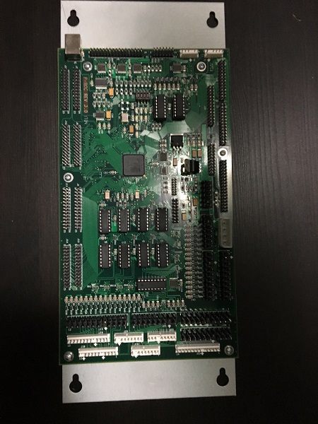
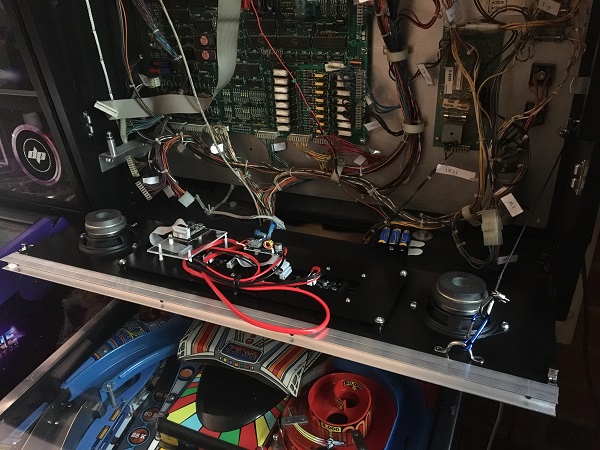
I’m long overdue for an update on my PINBOT 2.0 project. It’s been moving slower than I had hoped, but there’s no real rush here. Also, for a 2.0 project like this, a lot of time gets spent on code and it’s not easy to translate that into interesting posts for people to read. But there are some interesting things to cover 🙂 Thanks to a mate of mine, I’ve been able to source a P-ROC board on loan which will allow me to move the project from my desktop PC into the physical machine to actually test! This is very exciting to say the least! I’m on the look out to buy my own though as I’ll eventually need one – but for now this will do.
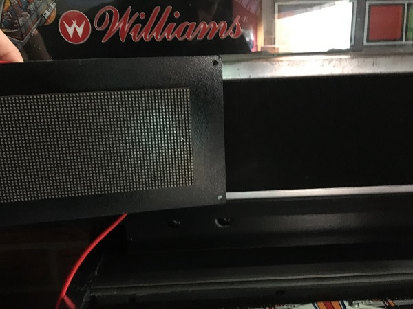
Once I had the board, I started thinking about what needed to be put in place to get this into my machine. The more I thought about it, I realised there were a number of things I had been putting off that needed to be done before it was possible. The first is the display panel. As mentioned in earlier updates, I’m using a colour PIN2DMD LED display. I had hoped to create a replacement speaker panel with the display attached to it. Sadly though, the display is taller than the speaker panel. This means that along with creating a new panel for the display to attach to, I’ll also need to look at doing something different for the translite as the original will no longer fit once the new panel is installed. I don’t plan to modify the original translite, so a new one is the only real option here. That’s not going to get in the way of development though and I’m happy to put that off for a future time though.
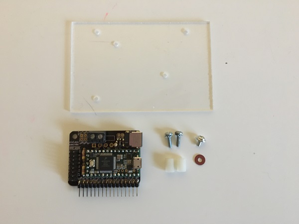
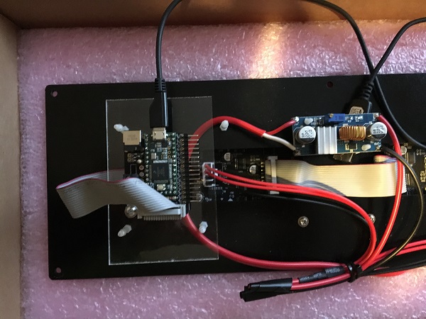
Before I look at mounting the display to anything, I need to get the Teensy PCB attached to the display itself. Up until now, while testing on my desk, the Teensy board has just floated off to the side. This needs to be mounted properly for installation into the cabinet. The PCB is a lot smaller than the original shield that comes with the PIN2DMD display, so it won’t install directly to the existing PCB stand offs. To get around this, I grabbed a spare piece of acrylic off the shelf, along with a couple of nylon posts, screws and washers. Holes were marked and drilled onto the acrylic to match the existing PCB stand offs.
The Teensy board was then installed onto the acrylic, which was then installed directly onto the existing stand offs.
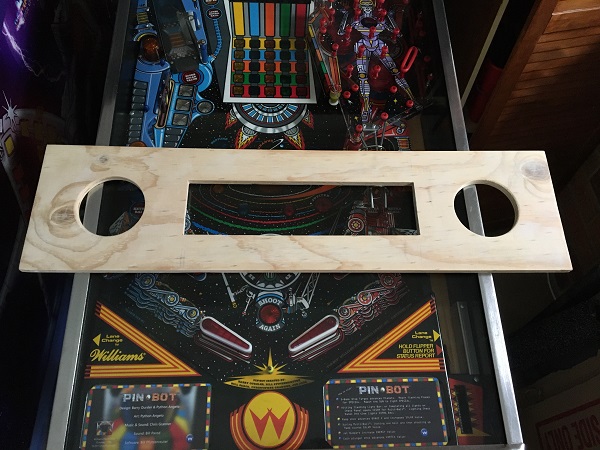
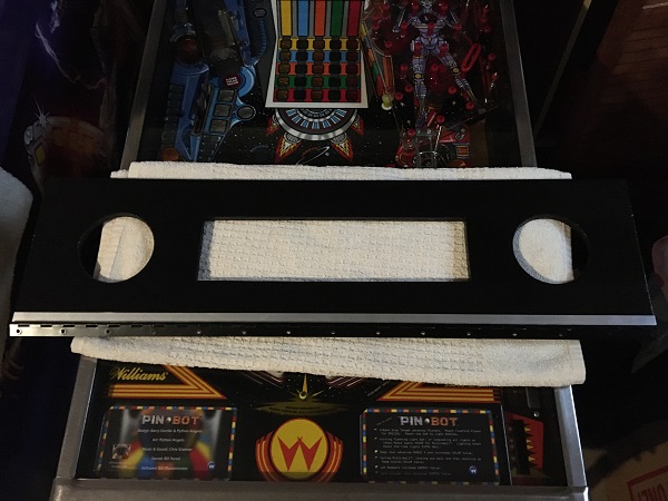
I decided to use the updated display panel from BoP 2.0 as a model for sizing on the new panel for my project. The main difference is the width, with PINBOT having a wider headbox. A new panel was measured up and cut to size, along with holes for the speakers and display.
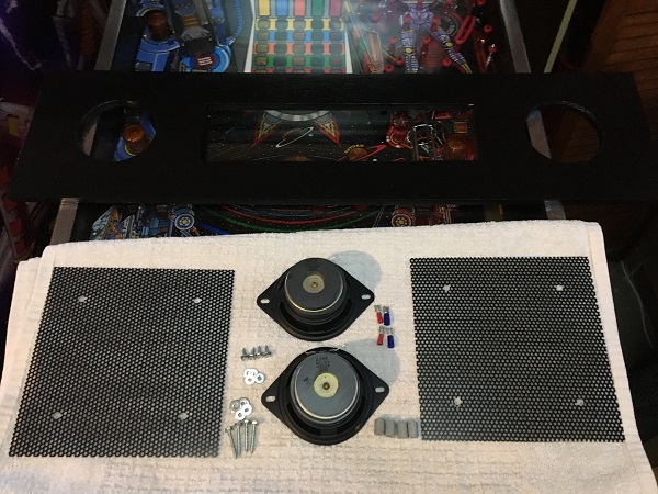
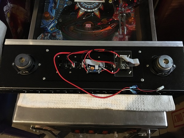
The panel had filler applied to all the small crevices on the surface. Once dried, both sides were sanded. This process was done twice before 2 coats of gloss black paint was applied. I sourced two small speakers out of my spare parts to install. These are actually brand new speakers for a Pinball 2000 machine and only cost around $5. I plan to run with better speakers at a future date, but for now these will do the trick. I also grabbed spacers for the display panel to rest on, along with the screws and washers needed. Two grills were sourced also to install over the large speaker cutouts.
With the speaker panel coming along, I also needed to think about how to attach it to the cabinet. The way in which the original speaker panel is installed is not very helpful. It’s a metal bracket on each side that’s screwed to the headbox. This makes removing it a pain.
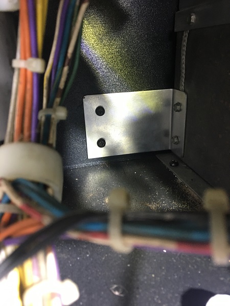
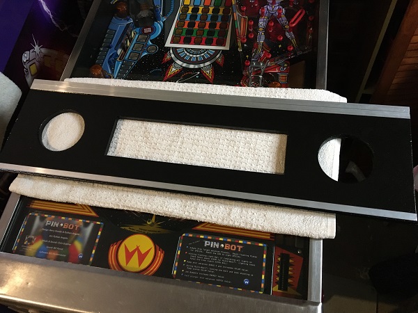
I had originally planned to just run with it for my new display panel, but because the new panel is taller (to fit the LED display), it will block the light panel in the headbox from opening. You have to have the light panel open in order to reach the screws for the speaker panel. This obviously won’t work with my new panel. So I decided to have my panel open up using a hinge along the bottom – very similar to what you would find on a Capcom game for example. This was installed, along with a piece of aluminium angle to the base of the display panel.
Although I won’t be installing a backglass during testing, I made my own H block for the top of the display panel. I was planning to use the plastic sort you can buy from pinball parts suppliers. But those are designed for WPC games and are not wide enough for these earlier Williams machines. Two pieces of aluminium angle were purchased, cut to size and installed on top of each other.
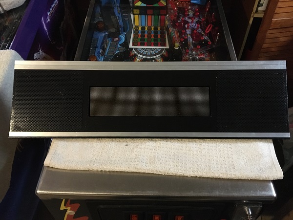
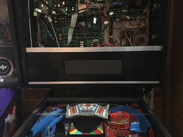
Finally the speakers were installed, along with the mesh covers and display panel. It was now ready to go into the machine.
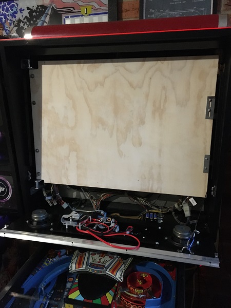
Nothing in pinball is ever simple though – especially when creating one 🙂 Due to the height of the new display panel, it won’t close properly as the new speakers and display board take up room where the light panel is.

This means I need to create a new light panel too. For now, the existing light panel was removed. Steel wire was installed for the new display panel to support it when opened (like you see on new Stern games), along with metal clips for the pane to lock into when closed. This display panel is only a prototype but has come up much nicer than I expected. The final version will have a printed artwork plexi overlay, but that’s something I’ll look at in the future and won’t hold me up for now. I’ll probably do that at the same time as the new translite so the artwork matches.
The original light panel was sized up and a new panel cut that will be installed when the game is running the 2.0 upgrade.
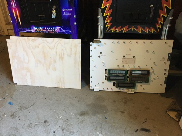
The brackets were removed from the original panel and fitted to the new panel.
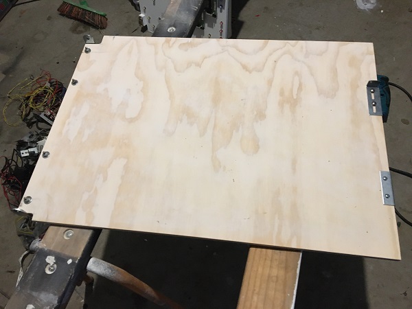
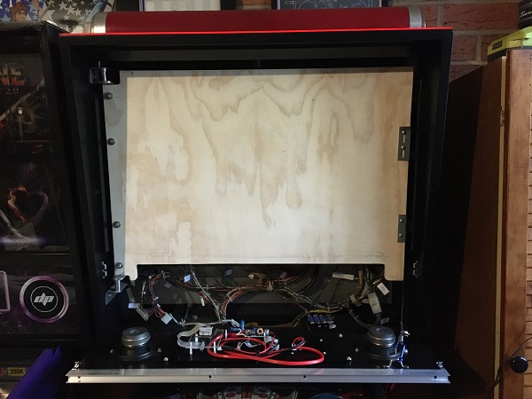
The new light panel was then installed into the cabinet to ensure position and size were good.
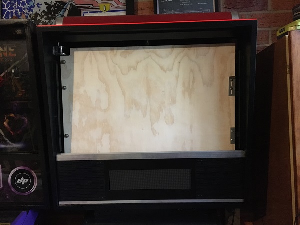
Lastly a section was cut out at the bottom so the display panel could be closed properly.
Success! The next step will be to paint the panel gloss white. I will eventually drill holes for lights and flashers to be installed, but will leave that until the new translite artwork is sorted out so the correct sections can be lit. I don’t plan to use the alpha & numeric displays as part of the 2.0 upgrade. It is possible to incorporate them using a piece of hardware from myPinballs that will allow MPF to communicate with them, but at this point it’s not in my plans for this project.
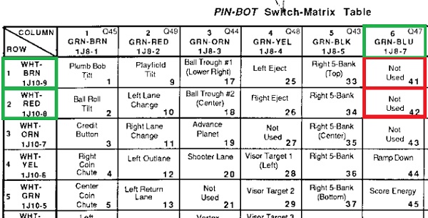
Pinbot has a lane change feature, which allows the player to cycle the lit “Extra Ball” inserts above the out lanes and return lanes. Unfortunately, these switches are attached to the EOS switches on the flipper assemblies. This is fine for game play where the flippers are active and will trigger the switches when the player actives the flippers. But what about using these lane change switches outside of the game for things like a service menu or flipping through the attract mode? We don’t want the flippers active then. Taking some inspiration from Scott Danesi on Bride of Pinbot 2.0, I’m going create two auxiliary switches that install with the flipper switches on the cabinet and hook up to 2 unused switches in the switch matrix.
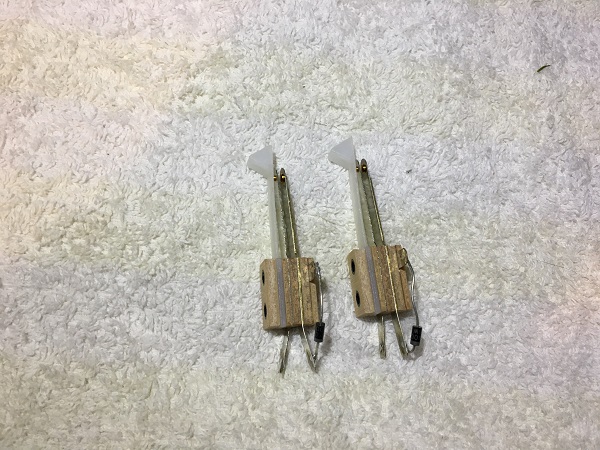
Two lane change switches with activating arms were purchased and diodes installed.
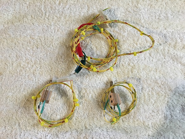
The switches will be wired up to the matrix using alligator clips for easy removal. They will also connect via IDC for easy disconnect from the switch matrix if needed.
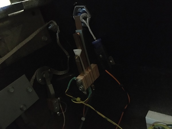
The switches were installed into the cabinet.
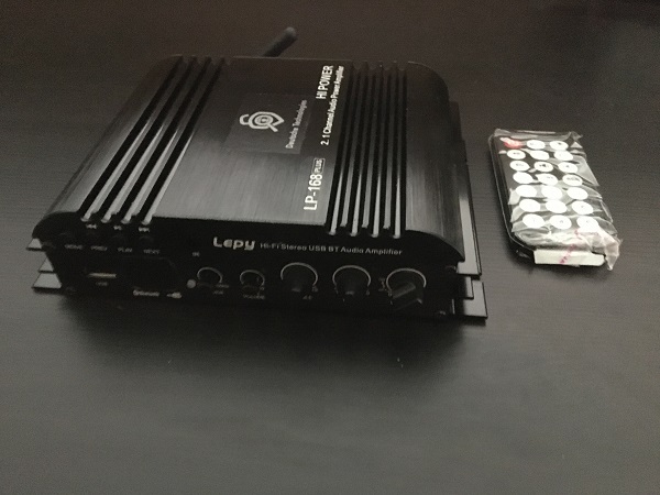
I’ve also been giving some thought to how the speakers and sub will connect up to the PC. Again drawing inspiration from Bride of Pinbot 2.0, I organised a Lepy 2.1 Amp that will (eventually) install just inside the coin door. This takes audio in from the PC which the speakers and subwoofer connect to. I couldn’t get the same model as used in the BoP 2.0 kit, but this one is close. It also has support for a remote and Bluetooth – neither of which I plan to use at this point.
With all that, I’m still not quite ready to get the game hooked up into my PINBOT cabinet. The items above tick off the big things that were holding me back, but there are some smaller items to address. I want to get the coil and switch test features of the service menu completed so I can easily test that I have the configs set up properly. These are already under development and hopefully won’t take long to complete. I’d also like to get some more audio into the game too. There’s also some cabling I need to sort out for the Snux board. I’m not even building a machine from scratch (..yet – that’s my next project) but it’s amazing how many things pop up that need to be done and slow the whole process down. That’s part of the fun I guess 🙂