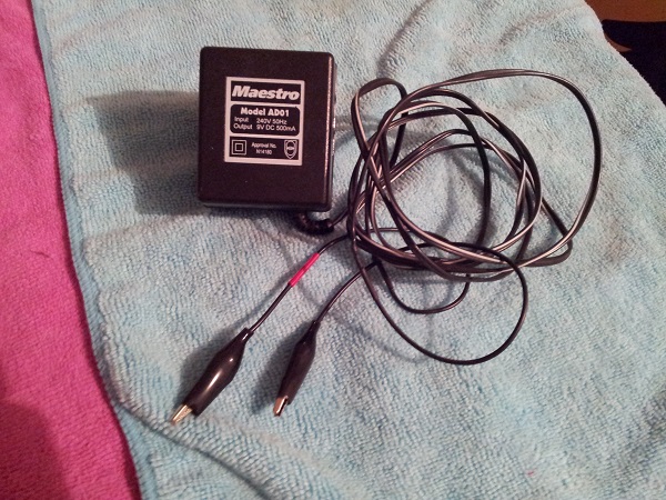
Continuing on from my previous update, the non working display is first on my hit list for this post. I’ve checked the cables and swapped the displays around to verify that the issue is indeed with the display itself. Last time, I tested the two UDN6118 chips on the display and they were OK. I did this on the chip pins however and not the solder joins on the rear of the board. This time, I flipped the display over and tested the chips using the joins. Both tested OK again. After some further research I decided to modify an old power pack that can refresh the displays by burning off the crap that becomes attached to the filaments. I was hopeful that the issue was simply a very faded display. For this, I found an old powerpack for a 28.8K modem I purchased back in 1995 or something. I’m amazed I still have it. It’s rated at 9V and 500ma. I replaced the connector with two alligator clips. I put some red tape around the positive lead.
The display was disconnected from the machine and a lead attached to the far pin on each side.
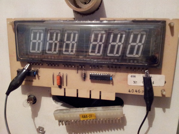
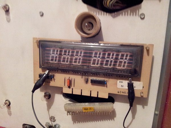
I then switched the power pack on for 10 seconds, at which time I expected the filaments to glow. This didn’t happen. I then put the charge pack on the player 4 display (again removing the display connector first). Switched the power pack on and found the filaments began to glow. So the power pack works, but nothing happens when I try to charge the player 3 display. On a side note, I left this on for around 10 seconds and then switched off. You need to be careful about how long you let the display charge. This is determined by the amount you’re supplying to it. As mentioned, in this case it was 9V and 500ma – so 10 seconds was fine.
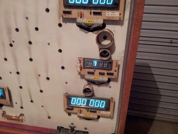
So that refreshed my player 4 display, but nothing happened on player 3. I removed the display completely again and had a closer look at how the display glass was connected to the pcb. There are a series of pins that come from between the display glass and are soldered to the display board. I found the first pin on the left had snapped off at the point it meets the glass. This would make sense as to why the the power pack does nothing and why there is no display when switched on.
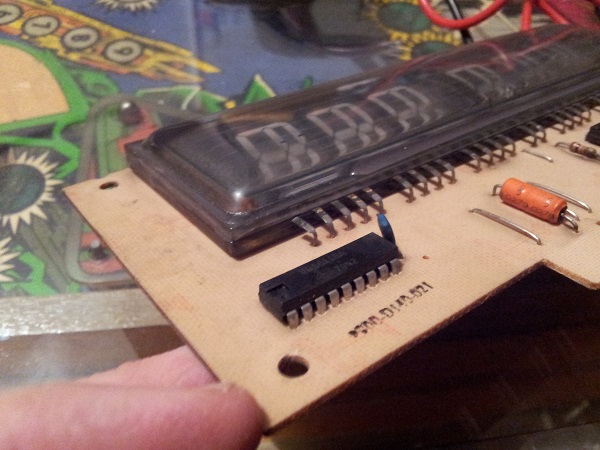
Sadly there was not enough of the pin showing from the glass that I could apply some solder and wire it together again. Thankfully the Aussie Arcade community came to my rescue with a replacement display – free of charge. Some amazing generosity. The new display arrived and was installed – I now have 4 working player displays (+smaller display for the credits / match feature).
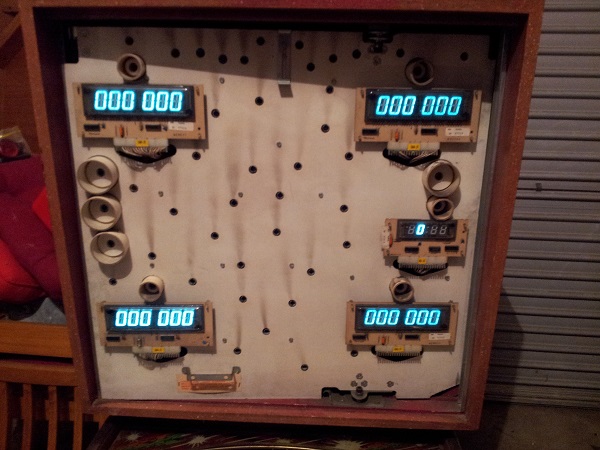
I’m not beaten on the display yet though and am willing to attempt to resurrect it by using my Dremel tool to carve out a very small section of the glass that will let me apply some solder and reform the pin. This is on my future to do list. Hopefully I will have some good news to report on this at a later time.
Now to turn my attention to the coin door switches. Currently, I can’t get the game to register credits or enter the test menu. This is controlled by the 10 pin J5 connector on the CPU board. These Gottlieb machines seem to be well known for their connector issues. This connector looks OK, except for 1 pin (6th from the left) which is a different colour to the rest. No matter though as I’ll replace all pins.
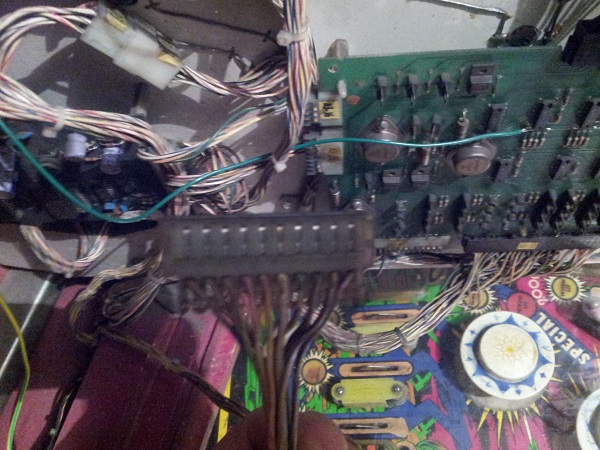
I had ordered a replacement connector for this from Docent, but I was made aware that the housing can fit other types of crimp pins. Since the order had not yet arrived, I decided to look at the alternative. By default they come with IDC pins, but you can extract these and replace them with crimp pins – which I believe are far more reliable. An order was placed with RS and a day later a pack of 100 pins arrived. Time to repin it and see if that resolves the issue. Here I’ve replaced the first 4 pins on the left – their colour is much cleaner and they also stand up a lot higher and will make much better contact with PCB.
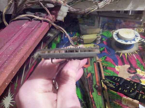
With the connector completely repinned, it was connected back to J5 on the CPU board. The machine switched on and the coin switch triggered. Success! The machine can now accept credits from both coin slots and the test button works also. No sound effect when the credit was accepted though.
Since I was in the headbox repining the J5 connector, I decided to try out the test button the sound board to see what would happen. With the machine powered on I pressed the test button, but nothing could be heard. The board is connected to the cpu board by a single connector, so I adjusted the connector as both ends and tried again. Same result. The volume pot is located at the front of the power board inside the coin door. I checked this and set it to mid way in its range. I made a third attempt on the sound test, but again no sound. I switched the machine off and removed the sound board for a closer inspection.
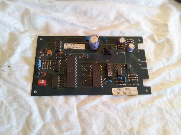
One thing that stood out was the large blue capacitor. I found I could wiggle this with my finger. Flipping the board over I could see both solder joints move as I gently wiggled the cap (highlighted with the red box).
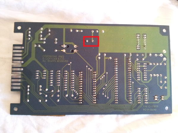
I got the soldering iron out and reflowed solder across the two points to get a solid connection to the board. I also used a small wire brush to gently clean the edge pins, to ensure a good connection with the connector pins. I put the board back into the machine and connected the cables up again. The test button again failed to produce any audio. Now I decided to repin the connector to the sound board and once done, fired the machine up and tested once again – success! It plays a small audio tune. I added a credit to the machine also which triggered a sound. So I’m happy that the sound board is working. A proper test will be to observe it during a game, but I’m not quite ready for that yet.
One final note on the sound board for now – there are two dip switches on the sound board which configure the sound (game sounds only / continuous sound and no attract sound / attract sound every 6 minutes). If you want to use the test button, you need to have these switches opposite. That is, one must be on and the other off – doesn’t matter which way. Having both on or both off will prevent the test from playing any sound.
Before I try starting a game or running through the test menu, I wanted to get those two broken drop targets replaced. The reason for this is in their current state, they don’t stay up and will trip their respective switches. This will interfere with my switch testing. I have some spare drop targets on hand which I’ll use. The drop target bank is quite large, containing 7 targets in all.
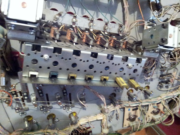
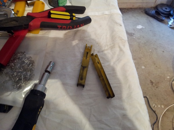
To get access to the targets, you simply need to remove the back panel via 4 screws. The panel can then be removed and you have access to the set of targets. There are two switches attached, which sit behind the drop target bank. These will need to be removed to get the plate out of the machine, but here, I’ve left them on. At a later date i’ll be rebuilding the entire assembly. The old broken targets were removed and some replacement ones added. One of the springs was missing, but I had some spares on hand.
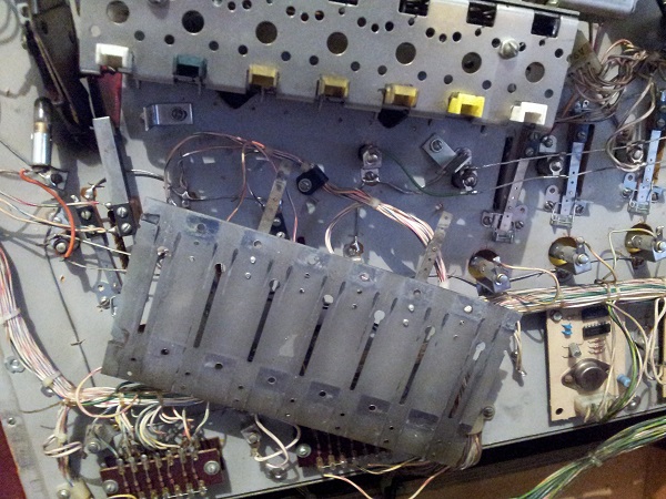
The base plate was then installed again and each target tested to ensure it drop when hit and then could be reset back to standing position. While I was in the area, something caught my eye on the two fuses located just further down to the right of the target bank. I tested these fuses the other day by removing one end from the holder and testing continuity. But with the playfield completely up, I had a much clearer view of them. I removed them and found the fuses were actually blown, but had some wire soldered across the ends.
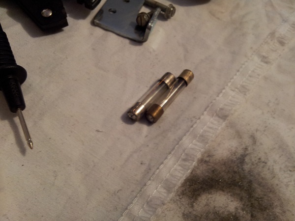
These two were tossed and replaced with brand new ones. A good example of why it’s important to eye ball and test them. Don’t assume they have the correct rating either. Seems like obvious advice, but quite easy to ignore or overlook. I was now ready to enter the test menu and see what issues came up. The playfield was lowered and machine switched on. After booting I entered the test menu via the button inside the coin door. I ignored the lamp test for now since I need to replace all the bulbs and the coil test can also wait. The switch test started with 99 shown on the display – which means all switches open. I pressed a few switches and found the switch number showed up – but it remained and failed to clear back to 99. I decided to repin the J6 connector on the cpu board which is in charge of the switches coming off the playfield. Once this connector was repinned, I tried the test mode again and had the same result. It starts with 99 and then when you activate a switch, the number shows up. It fails to clear back to 99 though. It also takes a few seconds before each switch is registered. I did some research and found this test mode behaviour is correct. The Sys80 test mode is not thought highly of and I can see why. I also ran the display test option and let it run through each digit – all passed. The final test was the memory test – this showed up successful too.
I decided to press the credit button and start a game, the coil and lamp tests can wait. The game began, sound played and I manually rolled the ball over targets and switches. The game ran although it looked like some switches became stuck on once activated. The pop bumpers work as do both sets of flippers. So it’s all looking really positive. I’ll need to investigate those switches and hopefully they just need a good clean and possibly given an adjustment. So the game isn’t fully playable yet. But I’ve got more connectors to repin, switches to clean and the playfield to rebuild. If things are still not right at that point, i’ll have to dig deeper.
Time for some more cleaning. The headbox wasn’t quite as bad as the base of the cabinet, but it still had a nice layer of dust across the surface.
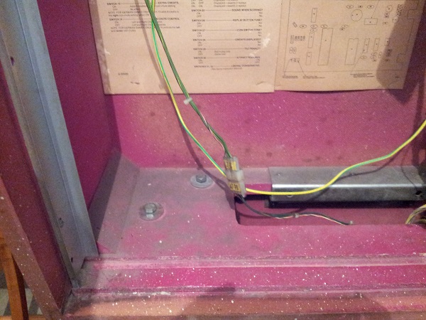
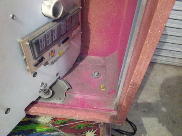
Various metal parts were removed from the headbox for cleaning also. Most weren’t too bad, but a few needed a good wipe down.
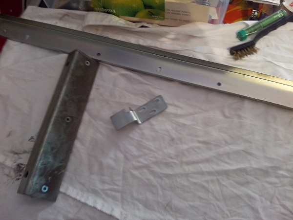
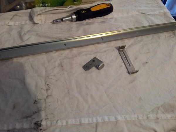
Once cleaned, the parts were put back into the machine and the base of the headbox cleaned too. Looking much better now.
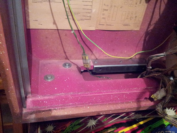
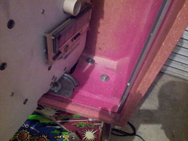
Next up was the speaker grill and the area behind it. The grill is attached via 3 screws underneath. Once removed the grill will slide out.
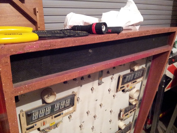
The grill was removed to receive a clean. A nice amount of dust has collected here over the years. The grill was set aside for a wipe down and clean.
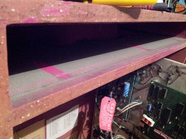
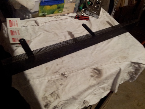
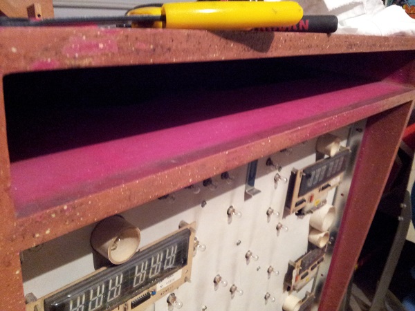
This was wiped down for the first time in 35 years and the grill installed back into the headbox. It’s amazing to see how much fade the paint has had over the years.
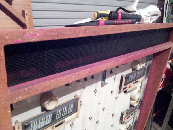
The last bit of cleaning I wanted to do on the headbox was the removal of the graffiti. It’s located on the two side panels (and a small section on the rear).
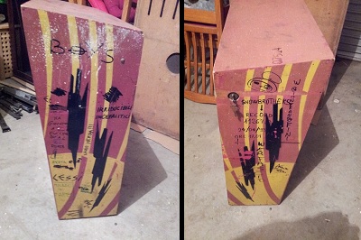
Eucalyptus oil worked the best here with some light use of a magic eraser. It was a struggle as some points, but eventually the majority of it was removed. The only parts I couldn’t clean off completely was where it had been scratched into the paint. It’s not perfect, but it will do.
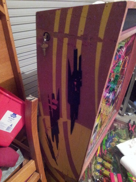
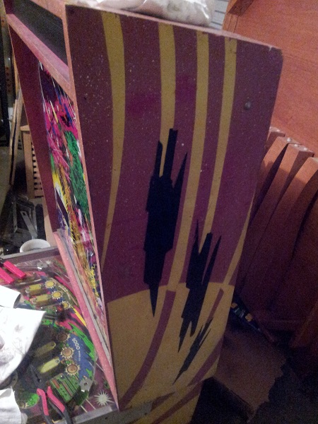
With the displays refreshed and headbox wiped clean (including the door), I decided to fit new globes across the headbox door. All #47s (no LEDs thank you), except for 6 spots across the top where I used blinking #455 globes to sit behind the Counterforce logo. I might purchase a few more and experiment the blinking globes in other areas behind the artwork. But for now, the headbox is looking nice and bright.
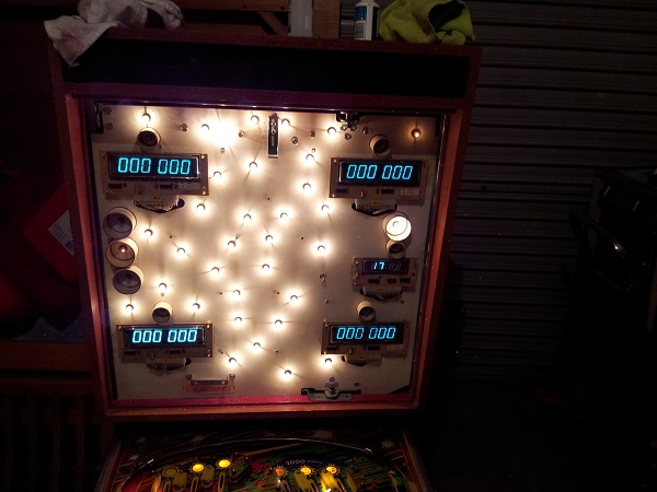
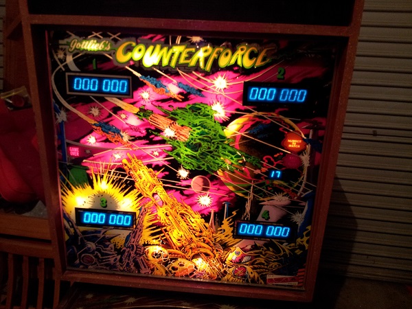
I wiped the backglass down to give it a nice clean. I was very careful on the reverse side and in fact left the lower section where the art has begun to peal alone. Lit up, I really love the art on this game. The mirrored sections are great – it’s something I like to see on the older backglasses. It’s a shame it’s hard to reproduce.
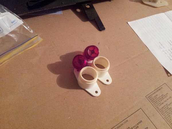
While I was cleaning the inside of the cabinet in my previous update, I had removed the flipper buttons for a good wipe down. They are still very usable, just dirty.
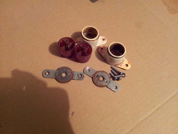
After some cleaning, they came up nice again. The two metal plates were scrubbed down with steel wool and wiped clean. They are now ready to go back into the machine. The flipper switches were given a light file to clean the contacts.
The plunger had also been removed as part of my cleaning and now was a good chance to rebuild it. The old plunger was completely dead. The spring was mangled and the rubber tip worn through long ago leaving a deformed shaft on the plunger. There are small metal shavings everywhere in this area because of it. My Pinbot plunger was the same. Surely replacing the 20 cent rubber tip isn’t that hard or outside a maintenance budget? No doubt this has resulted in additional damage to the machine over time 🙁
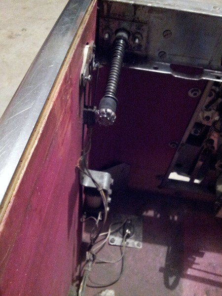
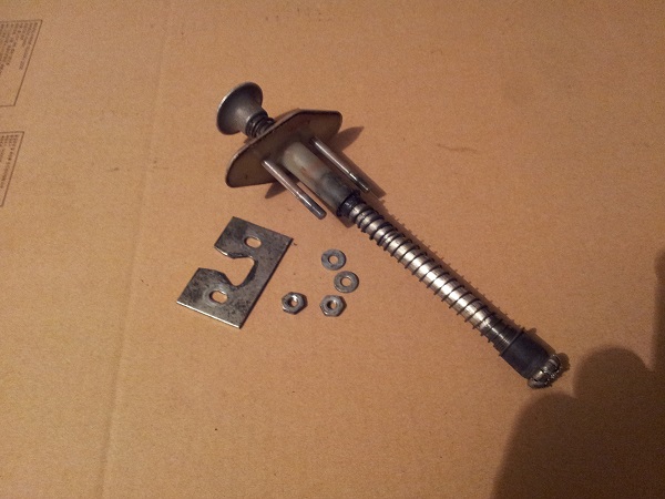
Most of this plunger assembly will be replaced. I have a spare second hand part for each bit of the assembly, so a “new” second hand shooter assembly was built. Some parts i’ll put through the tumbler and keep, but the rod and springs will be tossed. I’ll try cleaning up the rod sleeve before deciding if it’s a write off.
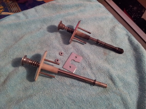
That’s enough for this this update. Next I’ll be running through the coil test and also repinning more connectors in the headbox. I think the smart option is to repin them all to ensure the best reliability going forward. Cost wise it’s not expensive, it’s just the time required. If I spread it across multiple nights after work, it won’t be too bad. I’ll test the transistors on the driver board too. I’m going to start rebuilding different playfield assemblies also, beginning with the apron and work my way up the playfield. I’ll sort out the switch issues as I go. Still lots to do, but at least I’ve taken huge steps towards having fully working game – so stay tuned..
