While I haven’t quite finished my previous (or should I say current) project – Pinbot, a new project popped up a few weeks ago that felt like a good opportunity – so I grabbed it. This time, I’ll be looking at a Counterforce machine by Gottlieb. It’s part of the Star 80 series and was released back in 1980. This particular machine started life in Italy, before being imported here to Australia. I was attracted to it as the gameplay looks kind of neat – seems like a mash of missile command and space invaders played out on a pinball playfield. Plus it’s an opportunity to work on a System 80 machine, which is something I’ve not yet done – so it should be an interesting experience. My last few projects have been restorations where I’ve spent a bit of money doing them up. But this project will be a little different. Due to the damage on the playfield, the machine won’t gain much value with everything else restored around it. The detail in the artwork makes it impossible to paint or touch up. Therefore, my plan is to keep spending limited. Any worn or damaged parts considered important will be replaced (globes, rubbers, broken drop targets, coil sleeves, etc). Anything that is still usable will be cleaned up and put back into the machine. So the goal here is to service all parts of the the machine, clean it up (wow does it need a clean) and repair anything broken to make it a fully functional game once again. I’ve set myself a reasonable budget to prevent over capitalising on it, but I may run into some nasty surprises along the way. So we’ll see how that turns out 🙂
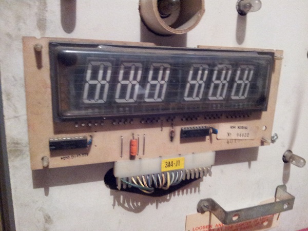
First contact – The machine powers up and appears to boot. It does not detect the coin switches to accept credits and the test button also does nothing. One display (player 3) is out completely and a single digit is missing from the player 2 display. Both player 1, player 4 and match/credit displays function fine. So there are a few things there to look at. I did a quick inspection of the display that was out and found it still had the small black marks in two corners, which means the glass is good. If they had been white, the glass would be broken and no good. The filaments still look OK and unbroken too. I’ll come back to this issue soon enough.
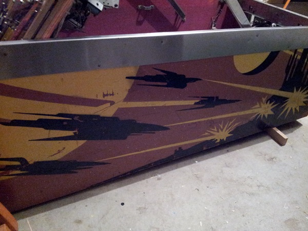
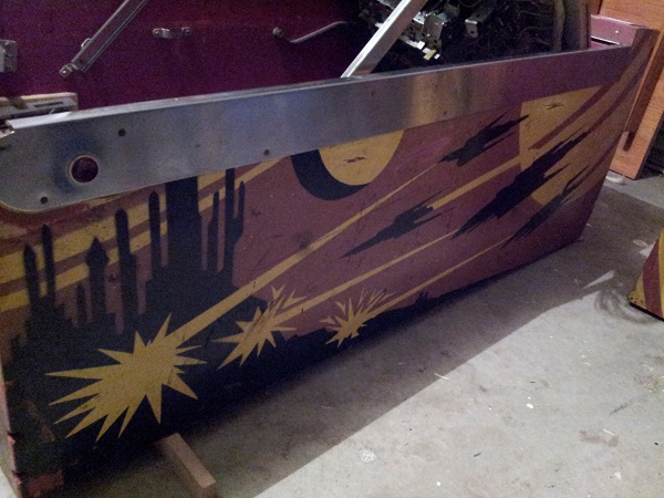
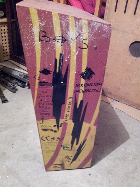
The cabinet isn’t too bad. There is the usual damage you would expect over the years with scrapes and scratches. I will remove the buttons for cleaning and give the side rails a rub down with some steel wool. I have no plans to repaint anything here as a good clean will be enough.
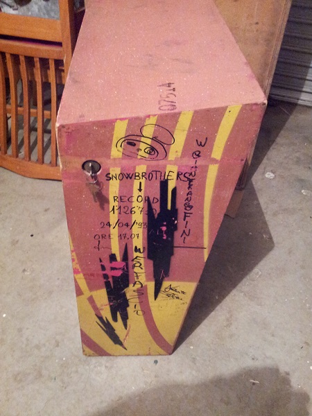
The head box is solid, although has some graffiti which will need to be cleaned off. I tried hitting this with a bit of eucalyptus oil and had some success. So I’m hopeful all of it can be removed. It’s interesting to see the scores listed and the years they were achieved. I’ll make a note of these and set them as goals for myself to achieve once the machine is operational 🙂 The lock still has the key and locks the backglass correctly, so no need to drill it out or replace anything here.
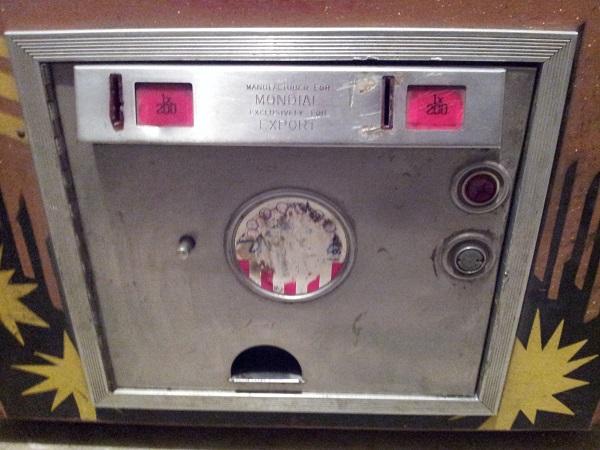
The coin door will need a good clean, a new Gottlieb decal and a new lock. I’m tempted to replace the damaged coin slots too, but will hold off and see what’s left in my budget once the rest of the machine is sorted out. At the very least, I will make up my own custom pricing plates, perhaps with the counterforce or gottlieb logo.
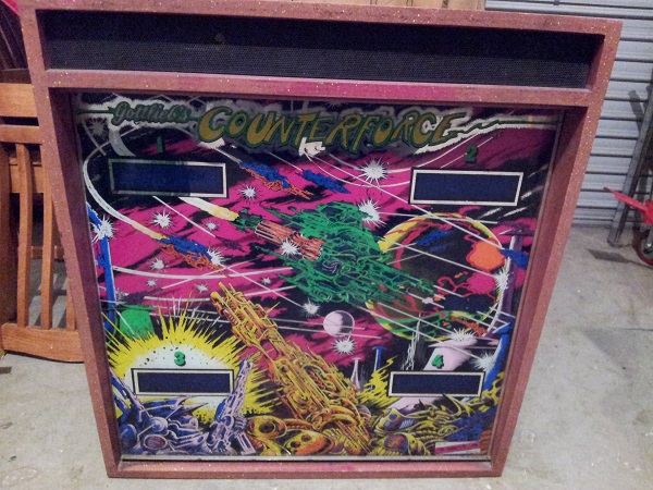
The backglass artwork has some damage in the lower section, but is otherwise fine. It needs a really good clean on both sides and along the lift channel. I may look at touching the backglass up where the paint had pealed, but that will be one of the last things I do if I decide to go ahead with it. That will require a bit of research first as to how to best approach it as I’ll only do it if I think it will improve the look. The long speaker grill is fine and just needs a clean. On quick inspection, this can be removed from inside the headbox.
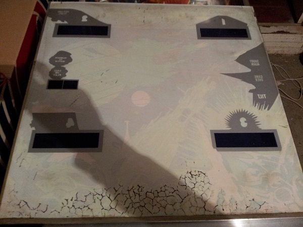
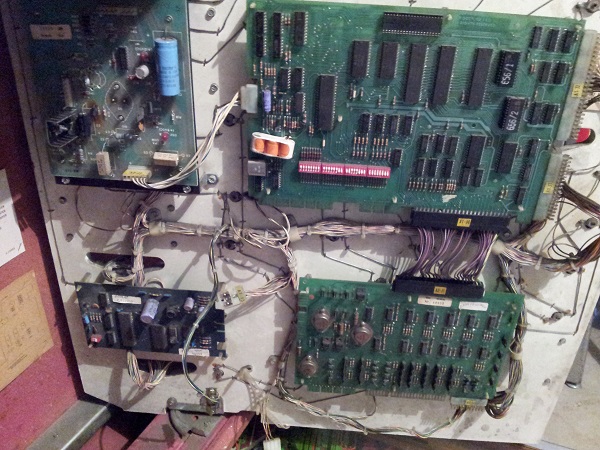
Inside the headbox, all boards are there. The original battery has been replaced thankfully, although I think i’ll replace this one too with a remote battery holder to be safe. I expect some connectors will need to be repinned, which may be the issue behind the coin switches not working and player 3 display being out. The ground mods have not been done, so this is one of the first things i’ll do before powering it on again and trouble shooting the issues. I’ll come back to this though. For now, I’m happy everything is there. There is some dust/dirt that I will clean up at some point too.
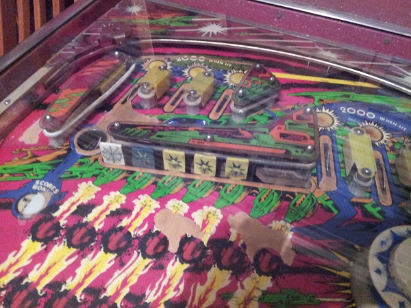
Now onto the playfield. The condition of the playfield is not great as it has a large bare patch in the middle. On closer inspection, this looks to a terrible case of mylar removal gone wrong 🙁 There is mylar still attached in various parts around the playfield, but it looks to have been lifted here and taken the artwork with it. Because of this, the machine won’t gain much value from me restoring it. I’m open to sourcing a better playfield for it however. So if one pops up, I’ll certainly consider going over my budget to add it to the machine. There are a few other wear spots, but I’m not too concerned about those. Once the playfield is clean, I’ll add some mylar patches to protect those areas as best I can.
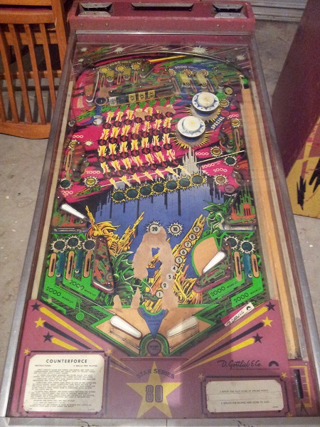
All the plastics are accounted for and will need a good clean. There is some slight warping on most, but that will be easy enough to fix. Only one piece is damaged, with two of its corners broken off. You can buy new plastic sets (for about $55US), but I’ll not worry about that in this instance. I plan to add some clean plastic washers around the posts here to protect it against further damage. Everything will need a really good clean. I’ll return to the playfield soon enough to strip it, clean everything, replace any broken parts and then install everything again.
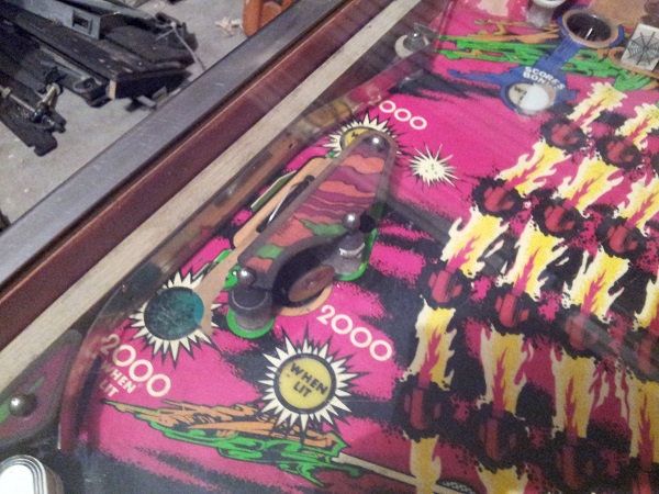
There are a few smaller bare patches up the top around the drop target bank. Two of the drop targets have their heads broken off. There is also a spider web target and a green target that I assume was installed to replace one of the original yellow targets. I have 2 spare second hand yellow targets to replace the broken two. I have some other colours also, so will see if I can work out a colour combination that is better visually that 5 yellow + 1 green + 1 white. I plan to make up my own decals to replace the worn stars.
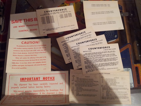
Time to explore under the playfield. Tucked away inside the coin door was a very old plastic pocket that contained the original operator and instruction cards. They are all in excellent condition – in fact I’d guess they have never been used. I had planned to recreate them, but it looks like the 3 ball instructions and my desired replay score cards are in this pile and will look great on the apron once cleaned up. This is excellent as it will help maintain the “used” feel of the machine and one less new thing to go on it.
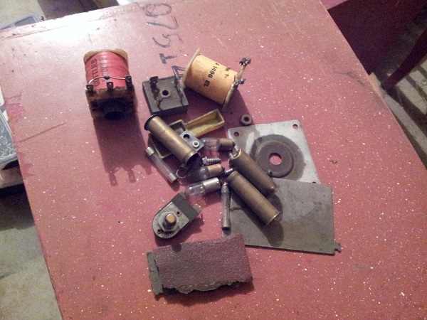
With the playfield up, I dug through the piles of dust and crap that had collected on the base of the cabinet over the years. A number of old parts turned up. Old fuses, brass coil sleeves, dead coils, mystery key, some sand paper and various other things. The fuses, globes and rectifier are dead, so these will be tossed. The old coil sleeves will also be tossed. The rest I’ll put into a bag and set them aside in case I find a use for them before the end of the service.
Now onto the base of the cabinet. I may need a shovel to get through this. It’s filthy. My plan was to first replace the power cable before I did anything, but I’m going to need to clean this up before I get that far back into the machine. The bottom of this cabinet has respiratory failure written all over it.
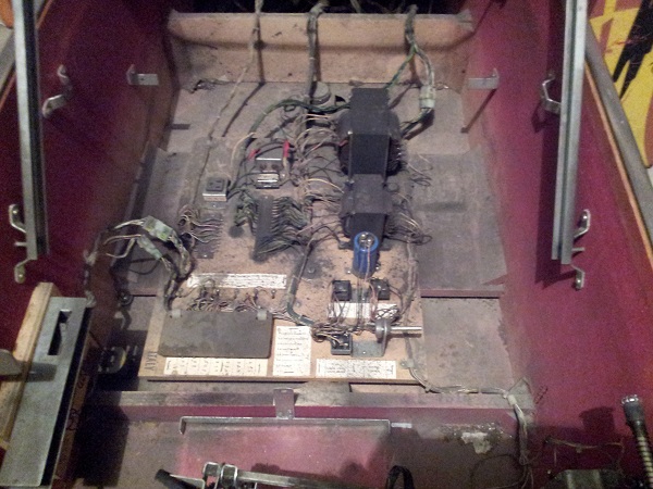
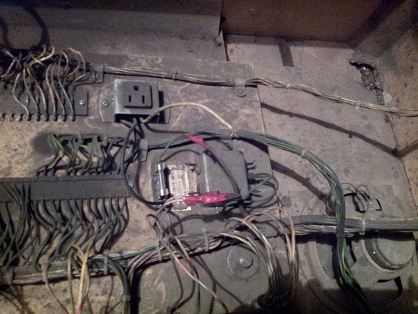
One thing that caught my eye when I picked the machine up was a cut wire going to the internal power point in the machine. Now looking closer I can see that the reason for this is the EMI filter has been completely disconnected from the system. The power cable would normally run into one side of the filer (active, ground, neutral). This has been cut out with the power wires directly wired to the wires that would normally be connected to the other side of the EMI filter (note the red tape that now covers their join). The machine will obviously run fine, but it exposes it to possible damage. I will be installing a new EMI filter and also a MOV to add protection. There is a really nice photo on ipdb.org by Chris Hibler showing how this area should be wired which is good for reference.
First however, a clean for the base of the cabinet. My plan is to begin cleaning from front and work my way deeper into the cabinet. When I get to the EMI filter, replace it and then continue on cleaning to the back. I got the vacuum cleaner out and removed as much of the loose crap as possible. It helped, but there was still much to be removed. The cashbox area was the first to receive a clean. Here’s the starting point:
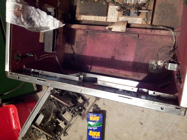
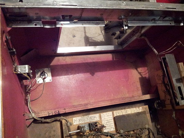
After a decent clean, it was very much improved. I took time to clean around the lock down bar receiver too and all of the metal brackets and parts in the area. A combination of steel wool, eucalyptus oil and isopropyl alcohol helped clean off the crap. You can notice the difference it’s by looking at how dirty the next section is.
One of the wires connected to the power on/off switch was barely connected, so I crimped on some ring connects and reattached the switch for a good connection.
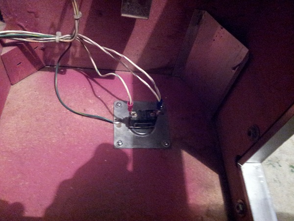
This was finished off with a cover to protect against touching it while hooked up to power.
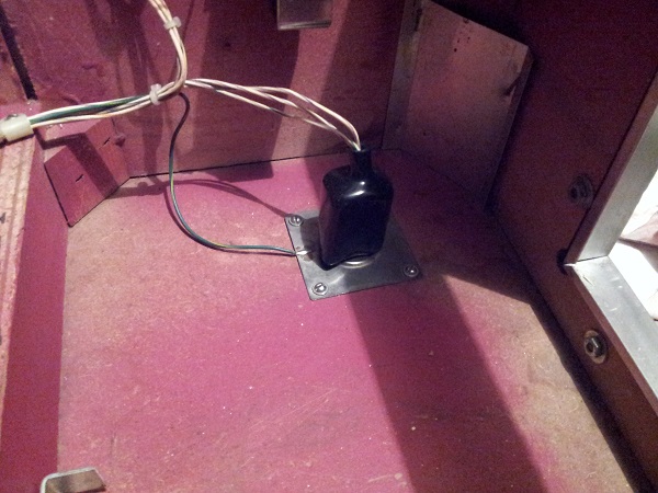
Also located in the front of the machine is the tilt mechanism and the knocker. Both of these were removed for cleaning. The tilt switch was cleaned and a new coil sleeve was added to the knocker. All wires were cleaned too as they were so filthy in placed you couldn’t make out the colour scheme, and I may need to be able to trace these when tracking down issues with the coin and test switches.
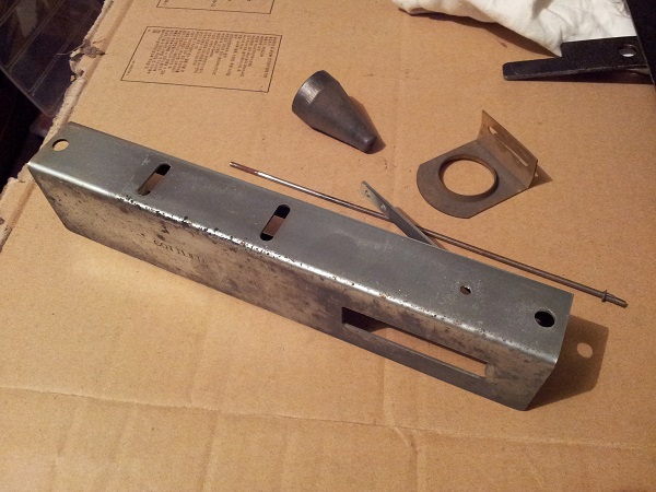
With the cashbox area of the cabinet now clean, it was time to move on the middle section which contains the powerboard. I chipped away at this section over a few nights. Cleaning the maintenance cards carefully as I went and giving the wires a wipe down too. Slowly, I worked my way to the line filter.
I decided to disconnect the active wire running from the fuse to the power point since it is not going to be used any more. At the same time I gave the plug and frame a good clean. The old filter was removed and replaced with a new one. A MOV was installed for added protection. The old mains power cable was removed from the machine and a new power cable installed. I picked a power cable that allowed for a another machine to piggy back off it. The wiring was then fixed up so now the mains wiring runs into the line filter, which then feeds into the machine.
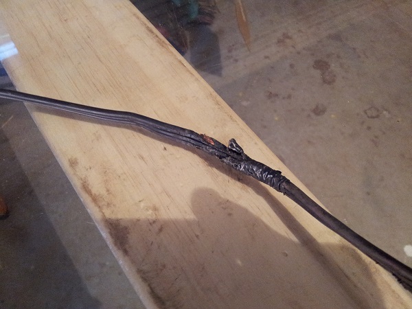
The old cable had 5 different sections where wires were exposed and covered up with tape. Glad to be rid of this.
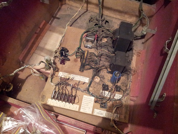
My cleaning then continued around the rest of the power board, until at last, everything had been wiped down and as much crap could be removed as possible. This effort annoys my Wife to no end as I can walk past a mess on the floor or leave the kitchen bench dirty for days. But i’ll scrub every mm clean of a Pinball machine 😉 The ground wires running to the two transformers were both loose, so these were cleaned up and then attached tightly to the frames to ensure a solid connection. The plastic cover that sits over the fuses was cleaned, so you can now actually see through it! The results are a massive improvement on the start.
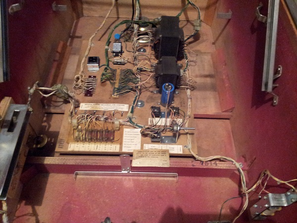
I then moved on to the back section of the cabinet. Again, this was vacuumed and the remaining filth removed to leave a much cleaner cabinet base. All cables were wiped down too. Before I switched the machine back on again, I tested the row of fuses at the front of the power panel. These all passed, however one of the fuse clips (the one on the far left) was cracked and not holding the fuse tightly.
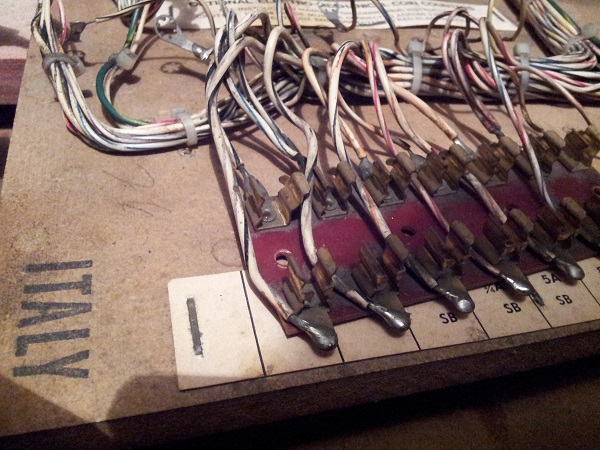
This was cut off and replaced with a new fuse holder.
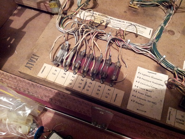
I tested the 3 bridge rectifiers located to the right of the fuses as well and everything checked out OK here too. Although this isn’t testing them under load, so the success might not be OK with the machine powered on. The original orange cap had already been replaced, so I left this alone. Since I had my DMM out and the playfield up, I located several fuses under the playfield and tested each one of them. All good too.
I did a few checks on the test switch, credit switch and coin switches to ensure continuity when pressed. These all passed. I put a thin piece of card between the contacts anyway to give them a gentle clean. Time to connect the headbox again and check the power board.
Before connecting any of the boards, I switched the power on. No fuses blew, EMI filter and MOV all good, and some of the playfield GI lamps lit up. I let it sit there for a few minutes without any issues. Now to hook up the power supply and check some voltages. The powerboard lit up with two LEDs which represent 12V and 5V supply. The board it upside down, which makes me think it’s been removed at some point in the past.
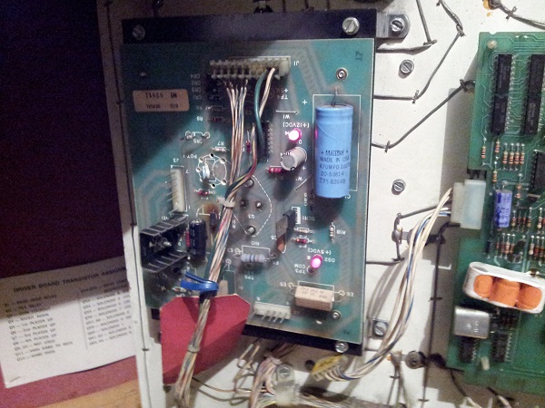
Using the schematic I tested several pins on the J2 and J3 connectors for 5V. I found that it was a little low at 4.68V. On the power board there is a small pot which you can use to adjust this up and down. After a few adjustments I had this at 5.15V. I then tested the voltages for the score display – all looking fine.
I decided to remove the board and reflow solder across the connector pins. It’s a bit of a pain as I found out you need to desolder the transistor on the back of the headsink. With the screws and solder removed, the board and heatsink could be split apart. Fresh solder was then applied to the 3 connector pins.
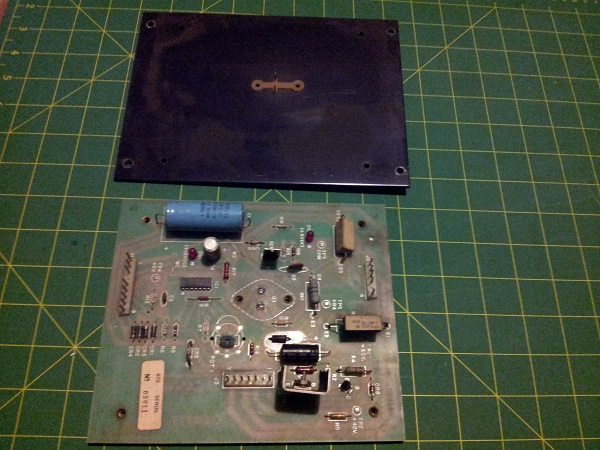
The board was then reassembled and put back into the machine. Again, I tested the voltages and all good. Now to do the ground mod. I’ve seen people mention there is no need to chain the ground from all boards back to a common point and all you need to do is add the additional pin to the connector that sits between the control board and the driver board. But I’m going to do it anyway. I’ve got parts on order from Docent Electronics in the US so I can improve that connector. While I wait for those to arrive, I’ll create the chain. Once the wires were in place, I tested continuity back to the ground point on the speaker. All good.
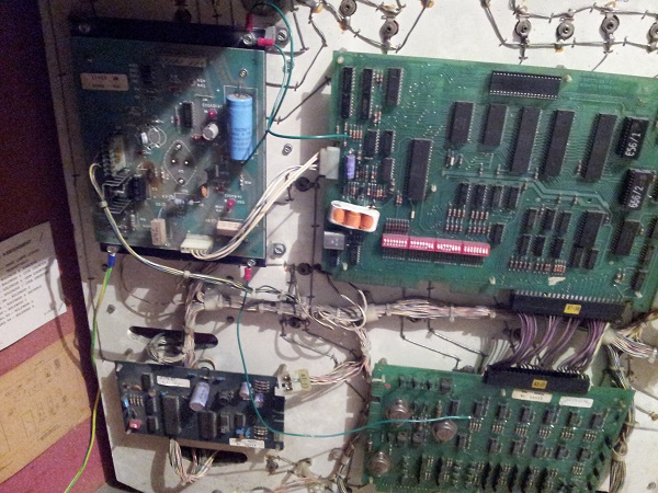
With all that done, I wanted to bring the control board online. I removed the connector between the control board and driver board (that’s the next step) and I connected up the power cable between the power board and the control board. The machine booted up fine and sat in attract mode.
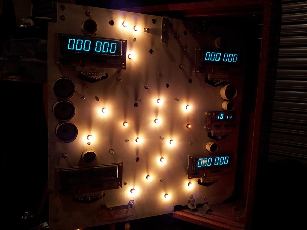
One issue there though, the credit/match display looks wrong with incorrect segments on. I switched the machine off again and played around with the edge connectors. I switched the machine back on and the display was good again. Some repinning here should get this more reliable.
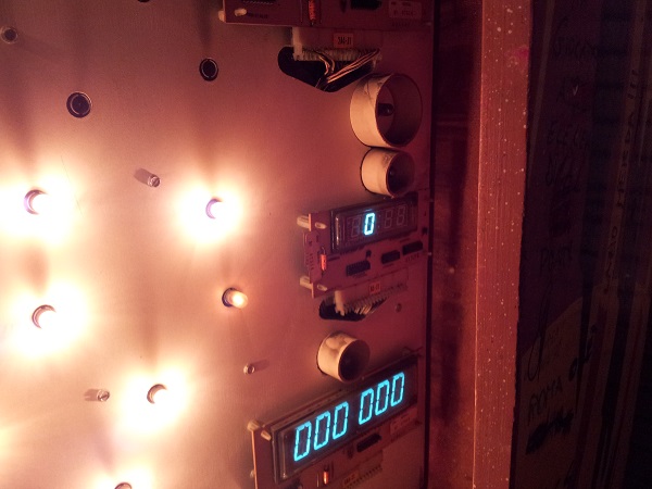
To round off this this opening update, happy everything was OK at this point, I connected the control board and driver board. Started the machine up again. After 5 seconds the machine came on, displays on and there was a small click from the game over relay. The lights on the playfield moved in attract mode. The coin switches and test mode switch still don’t work, so hopefully those parts from docent arrive shortly. Something to note too is the missing digit from player 2 display is now there. Most likely due to the connector stability.
I had a quick look at the player 3 display by testing the two UDN6118 chips with my DMM in diode mode. Pins 1 to 8 were all around 0.67 which is close to the desired 0.7. Pins 11 to 18 were all 0, which is correct also. So those chips are fine. I then swapped the player 1 and player 3 displays. The player 1 display works fine in the player 3 spot – so there is something up with that display. Oh well – gives me something to continue with while waiting for parts.
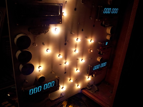
So I covered a whole lot in this opening update, but didn’t really make any progress on the issues I knew existed when I got the machine home (coin switches not working and display issues). I am however much more confident in the power supply to the machine, with the EMI filter (+ MOV) added, replaced the old crappy power cable, tested the power board and given the cabinet one heck of a clean. It also served as an excellent introduction to the system and helped me become a bit more familiar with its design. I have some parts on order which will hopefully help with some connectors. Those are at least a week away from arriving. While I wait, I’ve still got Pinbot to finish off and I’ll try doing some diagnosing on the display issues. I also plan to temporarily replace the two broken drop targets so when I can get a game started, that doesn’t interfere with the switch testing. Until next time 🙂

Hi Andrew: I’m a new pinhead in Canada and also have a Counterforce that looks surprisingly like what you have. Same wear and use characteristics. Mine had the added insult of having been knocked around pretty bad. No playfield glass, head box obviously askew, and lower cabinet divider smashed in. It looked like it fell off a dock or ramp. Any way am chipping away at mine, new power board, cleaning and reassembly of many parts, some new coils, repaired Pop bumper drivers, new pop bumper caps, new targets, lane guides, rubbers. Still need some new displays (actually smashed)and new switches. I am trying to get a printed mylar overlay for the damaged area of the playfield. It’s a real challenge to convert a digital photo to a proper scaled mylar applique, but I’ll keep trying. I actually had my game in play but the controlled lamps on the playfield all stopped lighting so am looking at a new problem. Hope yours is working well. Ill keep looking for updates but decided to reply to your first CF post because I found it interesting how similar the condition was / is to what I’m working on. I bought mine as a parts box, but now I want to get it to work reliably.
Hi John, Thanks for contacting me. I’m surprised to hear your machine has similar wear spots. I had thought most of mine were from a failed attempt at mylar removal (especially the sections through the middle of the playfield). Maybe the wear was just poor maintenance over a long period of time. Sounds like yours has been treated even rougher than mine – luckily though they are tough machines and with the right attention, can be brought back from the dead to live for a long time yet. Good luck with the printed overlay – I would have liked to try myself, but it would require a lot of time that I wasn’t willing to give. Have you re pinned all the connectors in the headbox? These System 80 machines are notorious for issues due to poor connections on the edge style connections on the boards. I ended up selling mine a few months back to make way for a new machine. A fun game though – would love to see how yours ends up if you manage to get the artwork overlay done! Cheers, Andrew.
Greetings from Italy!
Interesting to see your machine came from over here… 😯
I’ve picked up a few machines now that originated in Italy. Some pinball suppliers here source machines from overseas via large containers, with Italy being one source. I find it amazing to think about the journey a machine has taken through the years from starting in Italy, to its life on the streets, to private ownership and then finally here to Australia. I imagine some machines would have some very interesting stories 🙂