The last few updates I’ve done have been rather small.. It’s time for a jumbo picture update. In this post, I’m turning my attention to the door of the headbox (something you don’t often see covered in restore threads, so I’m glad to be covering it). It requires a decent clean and there are a few issues I need to investigate (I’ll get into as I go along). I also want to sort out the translite and glass with the aim of getting the backglass installed too. The main thing I wanted to do though is clean the door and head to remove as much of the dust that had built up over the years. Once I started on this path though, it ended up being a bigger job than I had originally thought.
The starting point – the door.
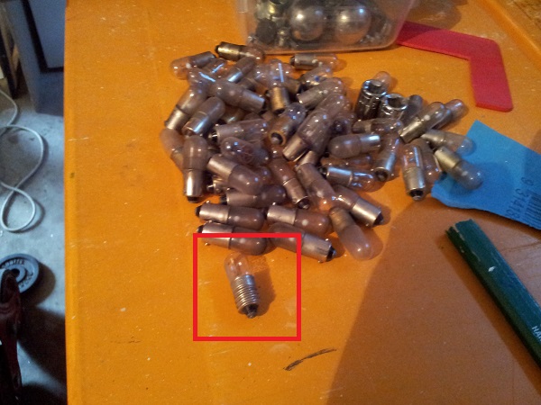
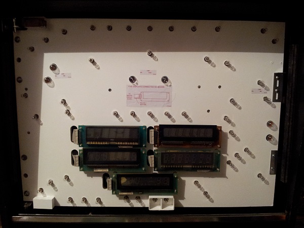
The first step was to get all the bulbs out of the board. There are 52 bulbs in total which consist of 4 x #89’s, 2 x #1251’s and 46 #44’s. All these bulbs work so I will be keeping many of them as spares and replacing them with brand new ones. All needed a good wipe down though as they had a hard layer of black dust over them. A handful of them were burnt and borderline dead – so subsequently thrown out. The main reason I’m keen on putting on all new bulbs in is it gives me a baseline for the machine. Just like replacing the rubbers. In 6 months, 12 months, 18 months, etc I will know how old these parts are and how much use they have been given.
While removing the globes I found at least 3 screw in types that had been jammed into the bayonet holder. These will be tossed.
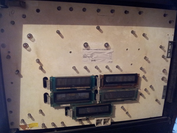
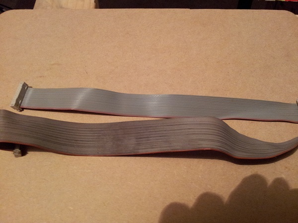
With the bulbs gone it was time to remove the displays. Nothing complicated here. All the displays work, so I don’t plan on touching them (outside of a clean). I do want to replace the 2 broken PCB stand offs though. The ribbon cables were very dirty, so I wanted to give them a good wipe down.
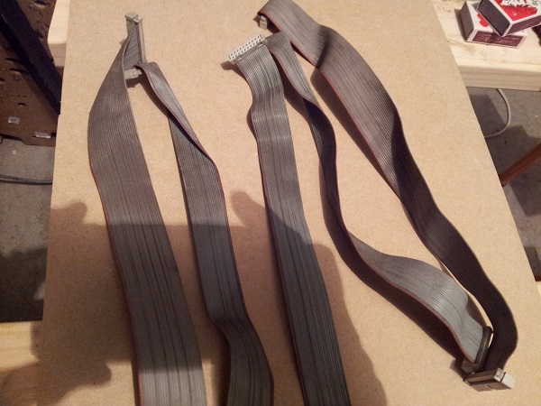
You can see a noticeable difference once clean. It was only once I started cleaning did I realise how dirty they had become.
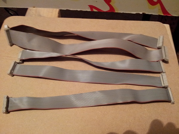
Finally all were done. You can still buy these new, but I couldn’t see any value in replacing them since all were functioning correctly.
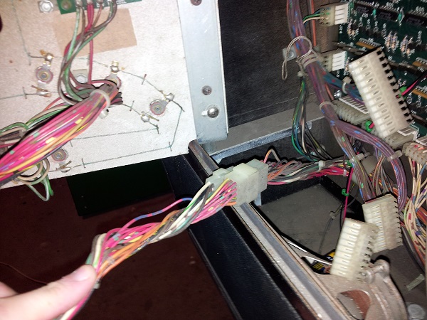
Next step was to remove the door. There are two small plugs which connect all the wires from the door to the rest of the machine. It makes working on these machines so much easier when components can be simply detached and then reattached. This is the sort of thinking I wish I had applied on my arcade machines – I had wanted to (and tried to in some respects), but wasn’t quite there yet with the experience in planning and design. Maybe I’ll return to them one day and make some improvements. There are a series of other connectors that plug straight onto the display board and these were removed also.
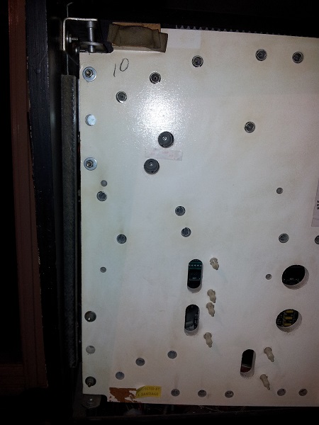
Once these were undone, I could unscrew the hinge and simply lift the door up and out. You might notice that the door appears to be on a slight lean down. This is one of the issues I want to resolve while I’m playing around in here. It looks to me like there is a small issue with the hinge. There is also a small block missing from the lower left which looks to have been broken off at some point. I want to replace this. At this point I had given the door panel a good wipe down, but I was not happy enough with how it was looking. I felt a coat or two of paint would really help brighten it. Would this make an overall difference when running? I’d like to think so – not sure if it does though.
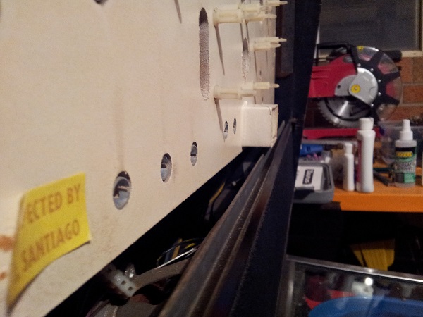
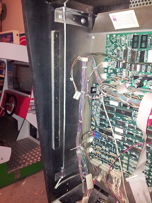
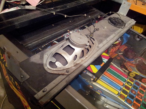
Before I remove the door, I’ll highlight the second issue I need to resolve. The speaker panel appears to sit too far back and will not allow for the backglass to be installed. You will notice the lamp shroud extends past the H channel on the speaker panel, preventing the backglass from sitting in position. The interesting thing is there is a light scrape against the inside of the headbox which gives the impression the panel has been pushed / knocked back – however the panel is securely screwed to the headbox and shows no sign of movement. I’ll be removing the panel when I investigate.
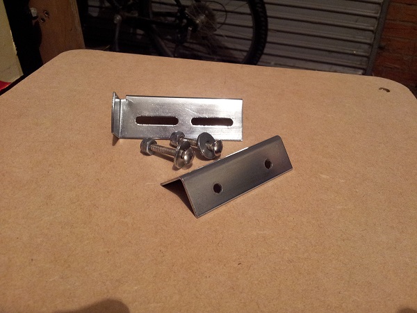
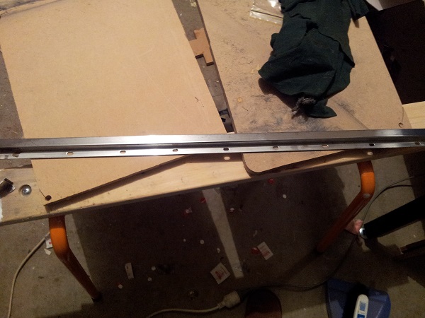
Before removing the door, I detached the latch connected to the door and the metal rails connected inside the headbox to give them a solid clean. As you can see, they are quite dull and dirty.
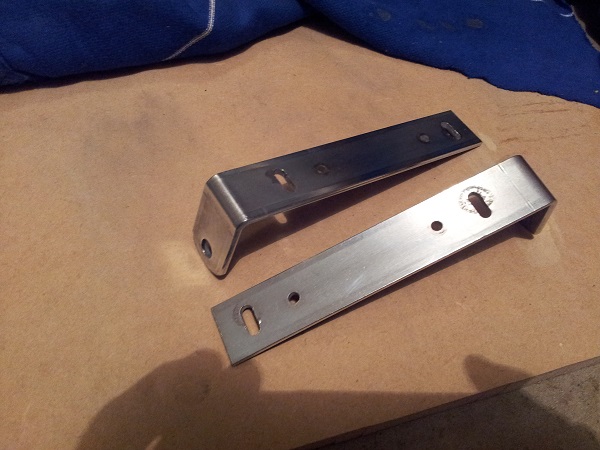
With some cleaning they look much nicer and it makes a real difference.
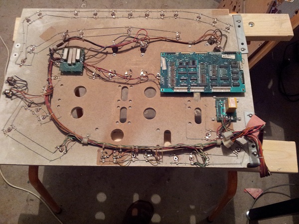
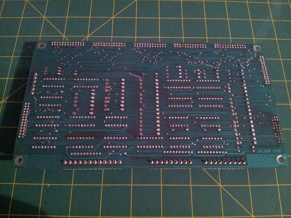
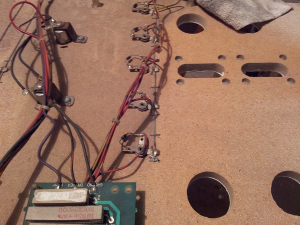
With the door removed, I set it down to remove the display board from the back before proceeding. There are 3 boards attached to the rear of the door. The display board, flasher board and a relay board. This side of the panel is covered in dust, although the photo doesn’t show it. The display board can be removed, so I wanted to get that off before flipping the panel over for painting to avoid damage. The other two boards are attached via wire, so i’ll leave them on as I work on the front side. I’m less worried about these two boards as I have spares. But I still need to be careful.
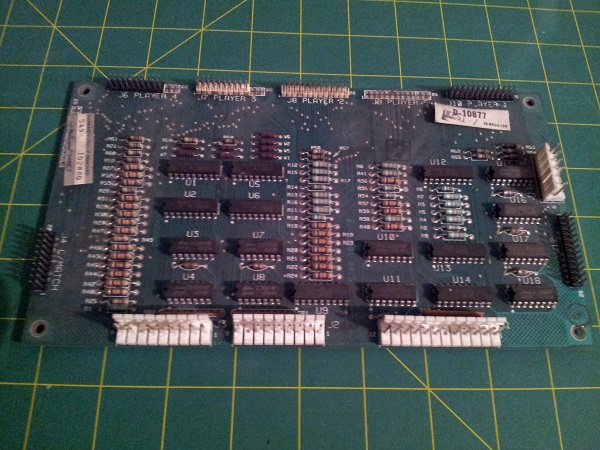
With the display board removed, I gave it an inspection to look for any issues or work done on it. Apart from being dirty, it was in good condition and showed no signs of work. There did appear to be a handful of cracked solder joints though, so I reflowed solder on those.
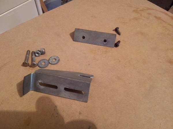
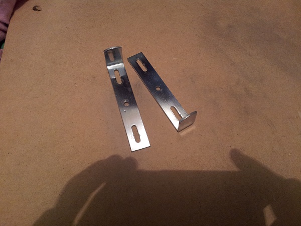
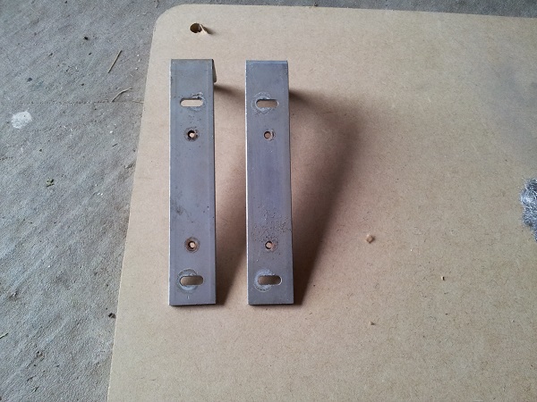
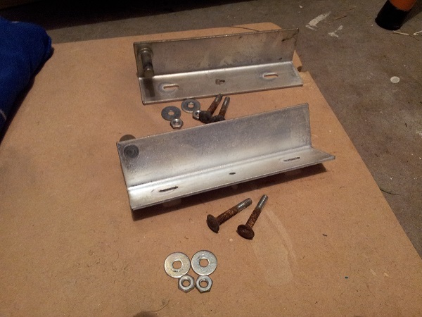
I now turned my attention to the metal hinge on the panel. I could see that one end was not aligned correctly and was the probable cause of the door sitting on an angle. I wanted to give the metal parts a clean anyway, so these were removed. They’re held in place with a two screws and two carriage bolts.
Like all the other metal parts in the headbox, they were dull and covered in dust and needed a clean.
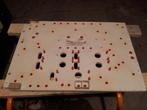
I now wanted to prep the front panel for painting. An interesting idea I saw mentioned was to put old bulbs in the sockets and just paint. This would ensure no paint got in the sockets. The problem with this though is I don’t like the look of brush strokes and was keen to use a roller. I wanted it to look neat. So I ended up putting tape over each socket hole and then trimming around it with a blade. This took awhile, but I got there. I did leave the PCB standoffs in though, so will have to use a small brush around these.
I still need to remove the old sticker. I’ll be replacing this with a new one as this had bubbled up in parts and would no longer stick properly. I’ll be reproducing this, along with the #89 and #1251 lamp stickers onto new glossy sticker paper.
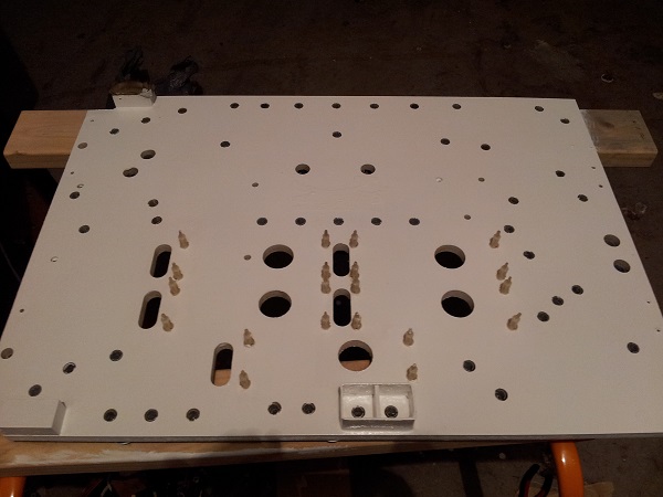
I ended up giving the panel 3 coats of a gloss white paint. There wasn’t any science behind my decision in paint – it was left over from an arcade project I did last year. The old state of the PCB standoffs now really stands out against the white panel. You can see the difference mostly around the burn marks made by the globes.
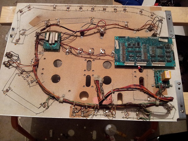
Now that that painting was complete I wanted to clean up the rear side of the panel a little. You can see here the dust on the left and the cleaned side on the right. While it doesn’t look all that dusty, a lot came off and I’m thankful to have that out of the machine now.
Next step was to install the display board again, along with the latch and hinge parts. If you look closely at this image and the starting point of the rear side, you will see the effort makes a difference. I imagine this is part of a machine that doesn’t get much cleaning attention over the years – so I’m glad to be taking the time with it now.
Before I put the door back into the machine and wired the displays up again, I wanted to clean the base of the headbox and also the other part of the door hinge.
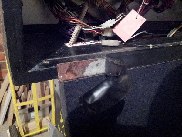
The door hinge is attached with bolts from outside of the headbox. These have not aged so well over time and have developed a nice layer of rust. I think they were originally black. A quick search online shows machines with both chrome and black bolt heads. I’ve got spare black ones of the same size (purchased originally for an arcade machine control panel – you know, back when I did that stuff ;)). The metal brackets are in great condition – just in need of a clean.
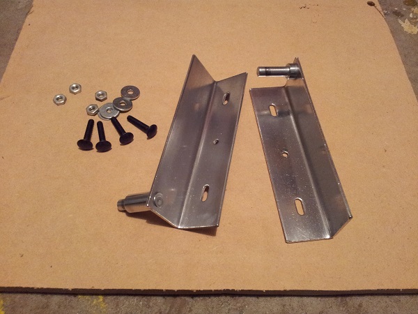
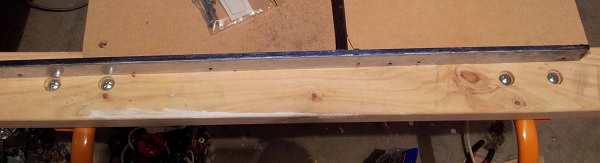
Much cleaner and new black bolts. The bolts are slightly shorter, but long enough to attach without issue.
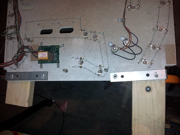
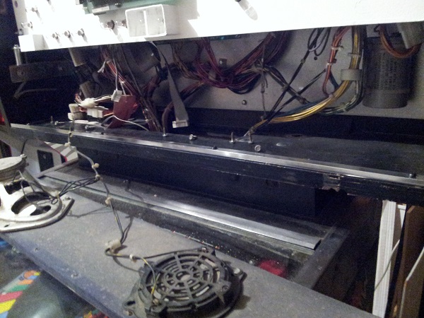
Next up was to clean up the inside of the head a little. I wanted to deal with the speaker panel issue anyway, so I removed that first. There are two screws that hold it in on each side. As you can see, the base of the head is quite dirty. There is a small metal bracket attached to the base which the speaker panel sits just inside of – I plan to pull this out for a clean too.
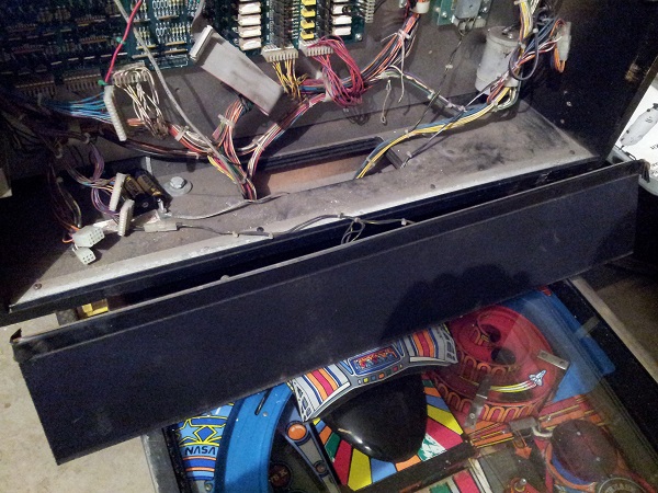
Half clean, half dirty – Amazing how much dust and crap has collected here over the years…
Meanwhile…..
A delightful package arrived from Greg at RTBB with some parts for getting the translite complete. Over the weekend I went to a local glass place to pick up a new sheet of glass to go with the translite. When getting glass quotes, I no longer tell people what it’s for. I found the glass quotes I received for the table top arcade machines I built were a lot higher when I showed the companies what the glass was for. Asking for the same glass requirement and simply mentioning it was required for a home project saw the prices drop by over $100. Anyway, this piece set me back $20 which I was quite happy with.
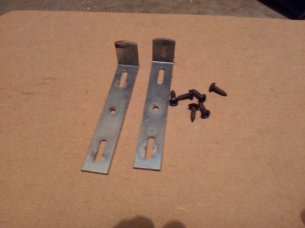
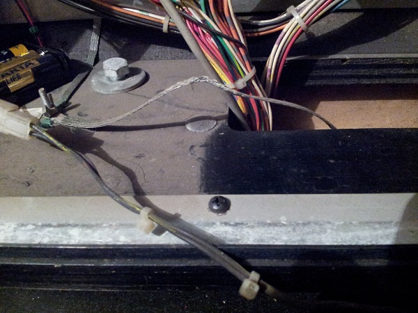
What I needed though was the black plastic trim to sit around the outside. Inside the Pinbot cabinet were a few pieces along with the metal lift trim. Problem was the plastic trim pieces were all different sizes and none of them correct. The metal lift was however correct, it could just do with a slight clean.
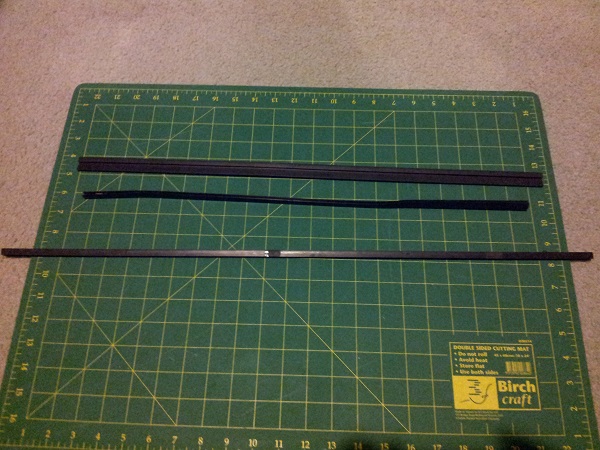
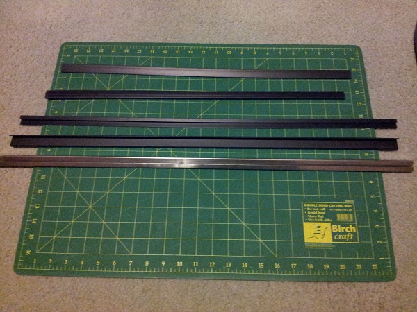
After searching online, I couldn’t find the exact sized trim required for this machine. However there was a close match that came as a kit. The lift channel was too short, but I won’t need the part anyway. The two sides will need to be trimmed by about 20mm each to make it fit correctly, while the top piece fits almost perfectly (it’s about 15mm short, but thankfully is hardly noticeable).
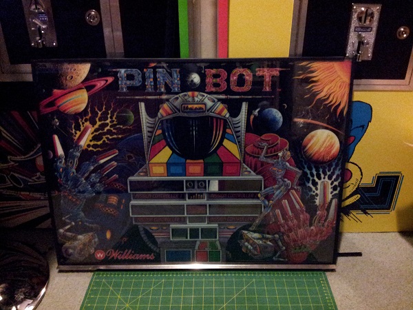
After some fiddling with the trim, translite and glass, it was finally complete. The translite was gently cleaned on both sides before installation (as was the glass). I hadn’t planned on doing this for awhile, but since I had the glass sourced, I figured I may as well do it. That way I can ensure the door and displays are all lined up correctly and the speaker panel is correctly fixed.
Back to the door….
The door hinges were installed back into the cabinet, along with the door. All new bulbs added with new stickers to replace the old ones.
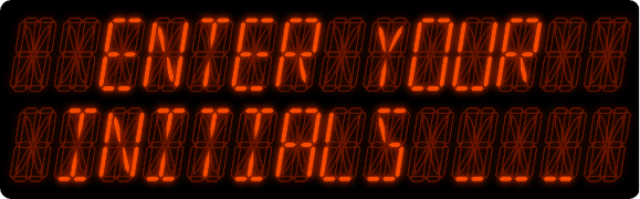
It’s come a long way since the first photo at the top of the post.
It’s looking good – can’t wait to see it lit up. But it will have to wait. There is still the little matter of the speaker panel to sort out. There are a few issues to fix with this speaker panel. The sound produced by the machine is fine. I love the music, sound and speech in Pinbot – it really delivers when playing the game and the audio has held up fine when I’ve tested the game. The speakers are attached via detachable cable too – so the whole panel can easily be removed.
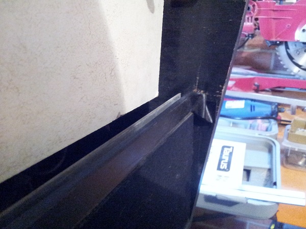
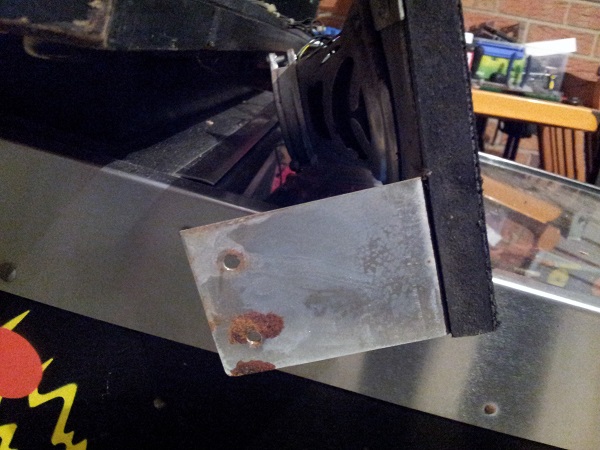
The first issue I’ve already mentioned – the panel is not sitting correctly. The second is the H channel across the top. It’s been covered in black tape. Pealing this back a little shows some rust and aging. The last issue is the small metal plate on the base of the head. This looks to have had black paint splashed across it – perhaps to “match” the black tape across the H channel. I’ll be removing the H channel to clean, along with the metal plate. If I can’t get the H channel to an acceptable level, I’ll use a nice glossy black spray (like I did with the metal brackets on the Pole Position machine) so it at least looks respectable.
(It’s not obvious from the photo, but the top of the rail is painted in a very thin coat of black paint. This should be nice a shiny).
The H channel is attached via screws on the inside of the panel. I’ll have to remove the speaker first though.
I took care of the base plate first since it was easy to deal with. The black paint was removed and given a good clean. I could then install it again. It’s much nicer now.
Next up was the H channel. Thankfully the rust was confined to just that small section on the left side. I removed the tape and proceeded to give it a clean. It’s came up alright, although I may have another attempt when the head is pulled apart again for the cabinet painting.
I decided to clean the two speaker panel brackets also since I had the panel out. Everything was installed back into the machine so I could then line up the correct position of the panel for the backglass. With the brackets lined up correctly, new screw holes were drilled and the speaker panel firmly attached. The backglass was installed and finally (…finally!!) the machine was powered it up to see how the backglass looked all lit up.
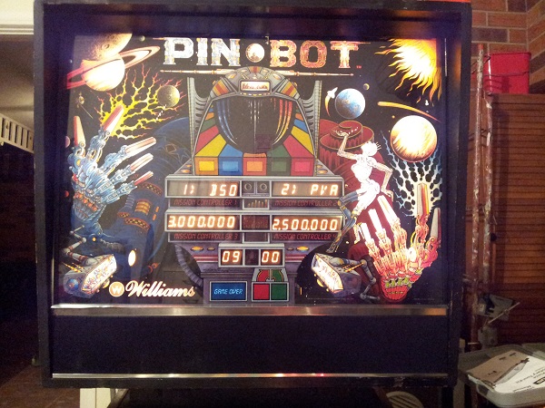
When I set out on this update, I had only intended to give the door a bit of a face lift. But once I got started, I couldn’t stop and kept adding more and more things on the to do list. Putting the backglass in and firing the machine up was really satisfying and a nice way to cap off this segment of progress.
My work on the head is now complete for the first phase of my restore. Phase two will see me remove the head completely, patching any defects before applying new paint with stencils. This will really finish it off. It will require me to remove pretty much everything again, but I feel better prepared for that now as I know how it all hangs together and what to do to get it back together. I will also use that opportunity to fix the pins on the power and flipper connectors.
Next up will be some work on the coin door I think, along with rebuilding the flippers and slingshots as I work my way up the playfield.
can you tell me what back glass trim “kit” you used. I also see some similar parts online, but if what you used works, I’ll most likely go that route. Thanks
It’s so long ago now sorry, I can’t recall.