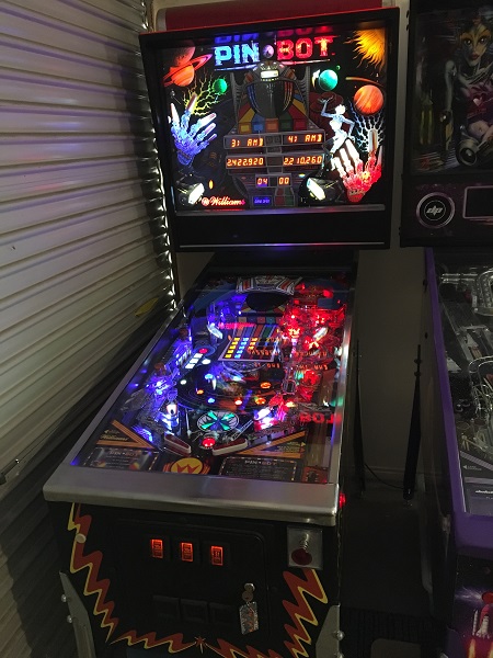
For quite awhile now, I’ve been toying with the idea of doing my own home brew pinball project. The idea first crossed my mind around 4 years ago, but I didn’t give it much time. Thoughts about doing it came again and again since that time, each being stronger than the last. But again I had always pushed it off as building a machine from scratch is more work than I was willing to do. It was more work than I could even get my head around. What about extending something that already exists though? Now that was something I could start getting my head around. Enter Bride of Pinbot 2.0. Owning a BoP 2.0 allowed me to see just what was possible with extending an existing game and how it all hooked up hardware wise. I was impressed with what a platform like P-ROC could do and the fact it was all reversible, means the game can be switched back to stock configuration again. I don’t have a large collection of machines that I could choose from in order to do this project, but there was one in my line up that stood out the most. Pinbot.
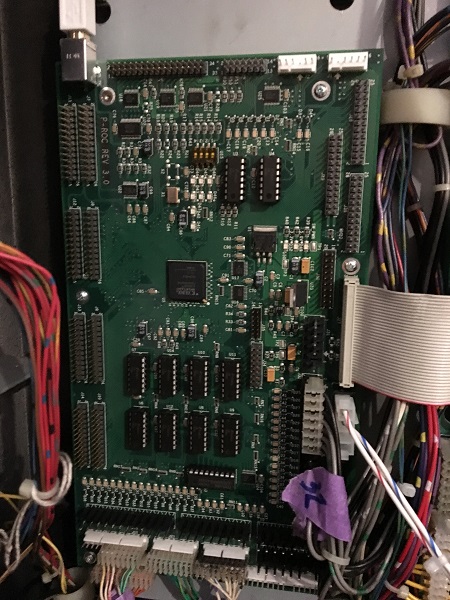
The P-ROC platform is made up several boards and bits of hardware, but for my purposes, I only need one – the P-ROC board itself. This replaces the CPU board and is driven by a computer. The computer can then run a brand new or extended rule set and communicate with the solenoid driver board for the coils. This one is sitting in my BoP 2.0 at the moment. For more photos of the set up in the headbox on my BoP 2.0, check out the restore posts (http://www.enteryourinitials.com/category/pinball/bride-of-pinbot-williams-1991/).
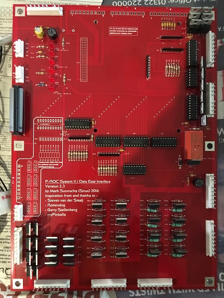
I’m sure many (OK, maybe just a select few 😉 ) of you reading that I plan to use P-ROC for this project stopped and said “Hold up. You can’t do that. P-ROC is for WPC games”. You’re correct, it is. But thanks to a clever chap nammed Mark Sunnucks, this is possible. Mark has created a Sys11 / Data East interface board that allows the P-ROC board to function in a Williams System 11 or Data East game. Mark played a role in the Dutch Pinball Bride of Pinbot 2.0 project, getting the original Pinbot running as part of the system. He has also done some incredible work with his own 2.0 / extended / second sortie project on a F14 Tomcat (see here for details – https://pinside.com/pinball/forum/topic/f14-tomcat-second-sortie-information-and-on-going-development). Mark and I crossed paths as a result of the restoration I did on my BoP machine and his help in getting me started on this project has been incredible. It’s an extra board needed for the project, but it opens up the options for me to use it in other games if desired too.
There are a number of frameworks you can use to write 2.0 or extended rule sets for a game on the P-ROC platform. The pyprocgame is quite mature now and is running many games out there like TNA and Houdini. It has a steeper learning curve, but you’re working at the code level and have far more control over what it possible. The other framework I looked at (and eventually decided on) was MPF – Mission Pinball Framework. This one abstracts you away from the code level and is more about working with configurations to drive the game. The learning curve is a lot lower and it’s well supported. The down side is you relinquish some of the control and features that you get with pyprocgame. Given this is my first dive into a project like this, I decided MPF was the way to go. Since MPF continues to be extended, the features I want may well turn up anyway – or I can look at coding them myself (I am a software dev after all). A couple of months earlier, I mentioned in passing to a mate that I was looking in to doing a 2.0 style project. Weeks later, he handed me a colour PIN2DMD display for free to use. I was speechless at his generosity! I had planned to use an LCD panel of some kind, but here was a free display to use. Could I use it with MPF though?
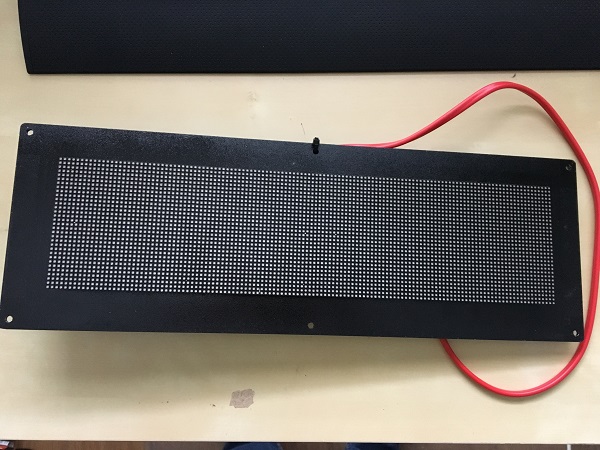
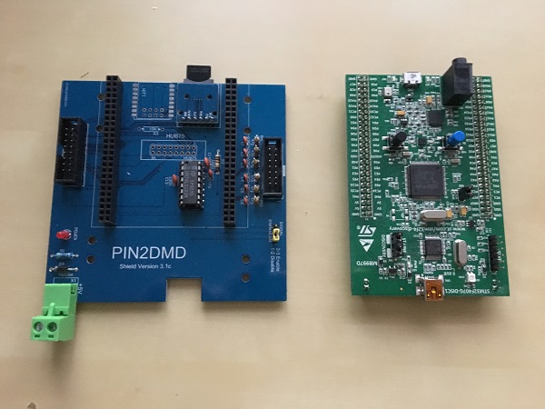
The Pin2DMD comes with a driver board on the back already, but how easily could this be used for what I wanted to achieve?
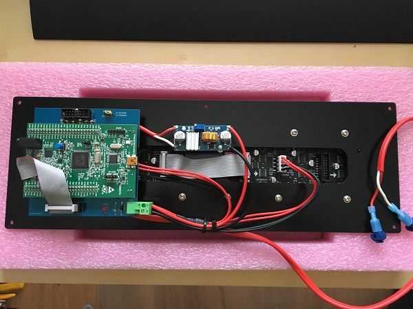
After some chatting with mark about the display, he informed me there was a way I could use it with MPF and in my project. To do it though, I’d need to remove the 2 large boards on the back of the display and replace them with something else. For this, I’d need a Teensy (https://core-electronics.com.au/teensy-3-2.html) and a Smart Matrix Shield (https://core-electronics.com.au/search/?q=smartmatrix). For around $90AU, the boards were delivered. The shield comes as a kit and needs to be soldered together.
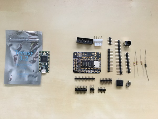
Putting the Shield together was a fun little project that took next to no time at all. It runs off 5V, as does the display panel.
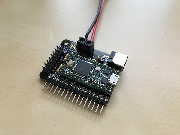
Next step was working out how to power the shield and the display. I looked at a few options, but the most suitable method for running it on my desk was an old ATX power supply from a PC. Luckily, work was gearing up to throw out several over them. I grabbed a couple and took them home so they could be live again. These power supplies have multiple 5 and 12V lines I can use to run multiple things at the same time.
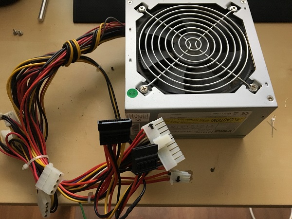
The only issue with these power supplies is you need to “jump” 2 wires in order to get them to power on when not attached to a PC motherboard. This is a simple task of joining 2 wires together.
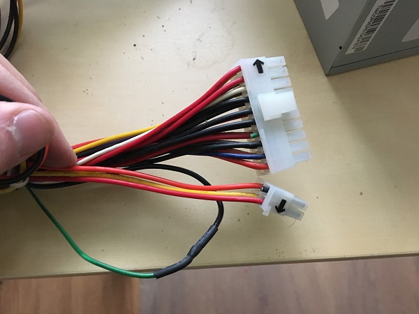
Next I needed to create 2 adapters to properly hook the display and shields up to the power supply with. An old splitter was perfect for the task.
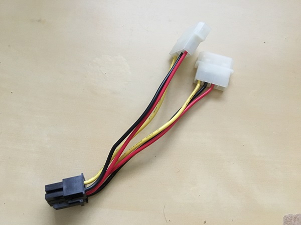
The unused wires were removed so only the 5V and ground wires remained. One was made for the Shield and a second for the display.
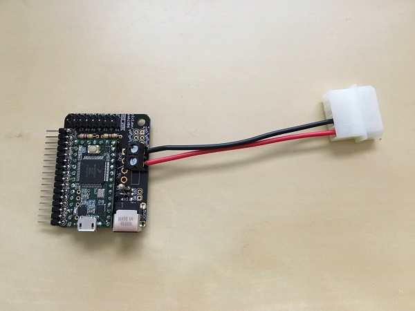
Now I could actually get the software loaded on to the Teensy. I had to install the Arduino IDE and Teensy drivers on to my PC. That then allowed my PC to interface with the board and upload a small RGB.DMD program that will drive the display.
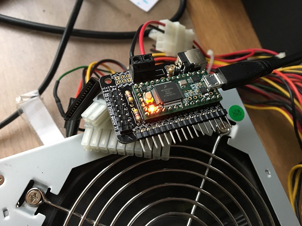
I now needed to remove the existing boards from the display. These were set aside safely and can easily be installed back on to the display if need be.
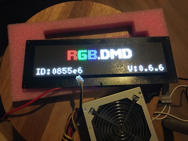
The Teensy + Shield combo was hooked up to the display via a ribbon cable and powered on with the display. Seeing the RGB.DMD splash screen was a sign of success 🙂
So I now had the display powered and the Teensy driving it. Now to do something a little more interesting and actually get MPF talking to it. The MPF framework comes with a demo game “DemoMan”. Which runs a series of splash screens and also acts as a game rule set, so you can start a game and activate switches via the keyboard to see a response. With a few config changes, I had MPF sending the display information shown on the virtual display (computer screen) to the real LED display panel!
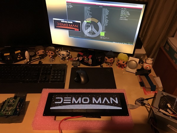
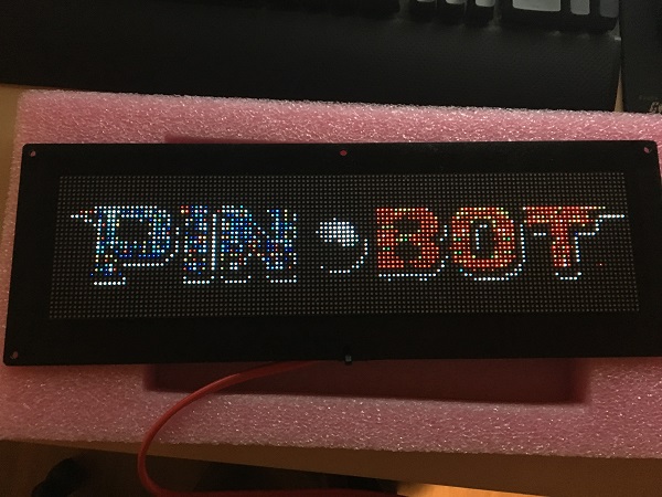
The DemoMan sample only runs in monochrome, so I replaced the splash screen with a colour version of the Pinbot logo. I didn’t spend long trying to get the image looking great – just a quick google search and resize to 128×32 pixels. It was only to test that colour was indeed being sent from MPF.
I was now keen to get my Pinbot Extended MPF project set up and begin working on replicating the attract mode. The MPF software has a “monitor” tool, which lets you define switches and lamps on a layout of the playfield, so you can test things from the comfort of your PC without having to have any hardware installed in the game. I took a photo of my Pinbot playfield and the defined all the switches, lamps and coils in the game. The square markers are switches and the round markers are lamps.
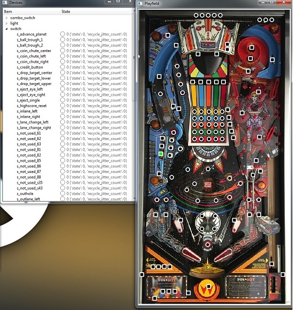
In the previous image, I have the lower drop target selected, which is detected by the MPF software. Right now it won’t do anything, but it’s the starting point for my game. This is like taking the glass of your actual machine and activating switches with your finger for testing.
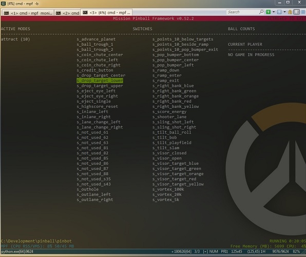
I somehow managed to condense weeks of effort into a series of photos and paragraphs above. No doubt I’ve skipped over several important insights, information and decisions. Right now I have a working display and also the starting point for my project. It might not seem like much, but it’s taken some work in getting to this point. Plus, it’s all I need in order to actually create a new rule set without hooking anything up to my Pinbot machine. My plan is to recreate the Pinbot ruleset as best I can as a learning experience with the MPF platform. From there, I should have enough knowledge to create the Extended version of Pinbot with DMD animations, new sounds, game modes and so on. I haven’t purchased the P-ROC board yet and will either look to source one locally or go to Multimophic direct. There’s a long journey ahead for this project and many road bumps to hit along the way. I’m not sure how often i’ll be posting updates and they may only be small ones when I do. But it’s a pretty interesting project I think and I’m excited to finally kick this project off!
