First item on my to do list for this update is to address a small issue with the the add a ball lamps. More specifically, the order in which the light up. There are 5 lamps in total. Each time you are awarded a free ball (achieved by hitting a lit WOW target), a new planet will light up to show how many extra balls you have been awarded. Right now, the order in which they light up is incorrect. They light up in the order 3, 4, 2, 5, 1.

These lamps are controlled by a stepper unit in the headbox. This stepper unit is used to control two features of the game. First is the add a ball count. Second is the 100K, 200K, etc lamps. These features are mutually exclusive, so you can only have one active in the game at any time. Looking at the stepper unit we can see a series of wires for the lamps. The stepper will turn clockwise, so the wires will be activated in the order blue, orange, brown, green, slate.
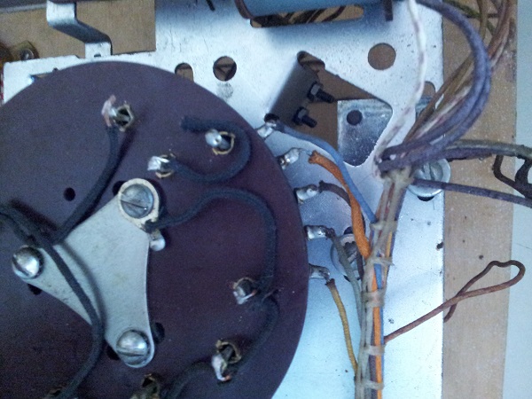
A quick look at the schematics shows that the order of the wires here is actually correct – blue, orange, brown, green, slate.

Now to check which wires run to the lamps. Here’s where the problem is. The wires are ordered (from bottom to top) – slate, brown, blue, orange, green.
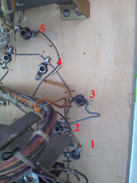
I desoldered the wires from the lamp sockets and then put them into the correct order. Now the add a ball lamps light up, bottom to top, in the correct order.
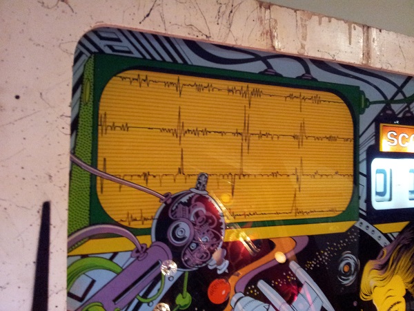
While playing around in the headbox, I decided to work out how to switch between the two play modes – add a ball and 5 ball. In 5 ball mode you can’t earn extra balls. Instead the WOW feature awards you a certain amount of points (based on another setting in the game). In this mode it’s much easier to roll the score – hence why the stepper unit is in this mode advances through 100K up to 1 million points. There is a section on the backglass which contains lamps for each 100K increment.
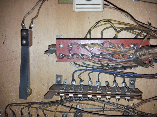
It turns out that switching between modes is very simple. It’s as easy as swapping the position of a jones plug. Here you switch between add a ball and 5 ball mode by selecting which jones plug to connect up.
After advancing the stepper by one, I can see that the unit now controls the lamps to show the score rolling.
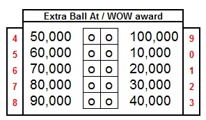
The last bank of jones plugs in the headbox are used to control the score adjust feature. This score adjust can be from 10,000 to 100,000 (in increments of 10,000). In add a ball mode, this sets the score at which a free ball will be awarded. This works also once the score has rolled back to 0. So having it set at 10,000 will award a free ball at 10,000, 110,000, 210,000 and so on. The wire allows for two values to be set at once. So you can award a free ball at 10,000 points and also at 60,000 points for example. When I first examined this, I was thrown off by the fact there were two wires running to this, both with two single connectors. One is for setting the add a ball free ball thresholds and the other for setting the WOW points awarded in 5 ball mode.
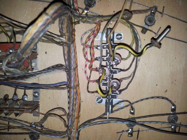
Unsure at first which was which, I did some experimentation. I found that the orange wire was for setting the add a ball scores and the green for the 5 ball mode wow award. Through further experimentation I was able to map out the score value for each of the 10 plugs (10,000 to 100,000). You can of course also leave the connector unused, so no free balls and no WOW award.
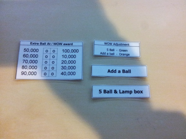
There are no labels or operator instructions in the headbox. If they did exist at some point, they have been lost to time. I decided to create a few, laminate them and attach them around their respective jones plugs to remind myself, or future owners, about adjusting the machine operation.
Happy add a ball mode is working correctly, I wanted to test out 5 ball mode and ensure the settings functioned correctly. From earlier in this update, I knew the stepper unit was correctly wired to control the lightbox and light up scores to 1 million. Time to test it in play. I swapped the jones plug over to enable 5 ball mode and set the WOW bonus as 20,000 to start with. I manually hit the 6 roll over targets to enable WOW mode and then proceeded to hit wow targets to boost the score up quickly. An issue I found here was instead of awarding 20,000 as per the settings, it was awarding 50,000. I’ll come back to that though. I rolled the score past 100,000, but the lamp in the lightbox to show 100,000 did not light up (the stepper unit did not activate). OK, so I need to investigate that.
Where to start? I know that the score reels have a 9th position switch (or carry switch) which is on when the reel is in the 9th position. This tells the game on the next advance, to carry across 1 to the next reel. In the case of 10,000’s here, there is no additional reel – but – for the lampbox feature to work, then surely it must need to know about this state at the time of advance so it can also trigger the stepper unit to advance. So i’ll start with the 10,000 score reel. On inspection, I found 1 wire that had broken off the small row of switches attached to it – sure enough – there was an empty switch lug on the 9th position switch.
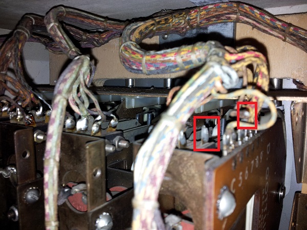
Getting to the switch through all those wires (with a soldering iron) would be a pain, so I decided to remove the score reel to allow for better access. But how to do that? Well at the base of each score reel is a small plastic (or nylon?) tab which you flick to the left – that then allows you to pull the score reel back and remove it. Each score reel has one of these, preventing it from sliding out.
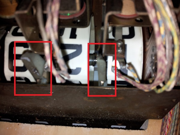
The wire was soldered back onto the 9th position switch. While I had the score reel out, I decided to manually step the reel through from 0 to 9 and watch the state of the switches. There are 2 other sets of switches in the area. The first (on the far right) are the home (or zero position) switches. These close when the 0 is shown on the reel. Once the reel moves to 1 (up to 9) the zero position switches open, closing the second set of switches. The 9th position switch remains open until 9th position. I found this switch needed some slight adjustment also as it was a bit too far away to make good contact on 9th position where it should be closed. I manually stepped through the reel a few times to ensure all switches were correctly changing state after my adjustment. Everything looked good.
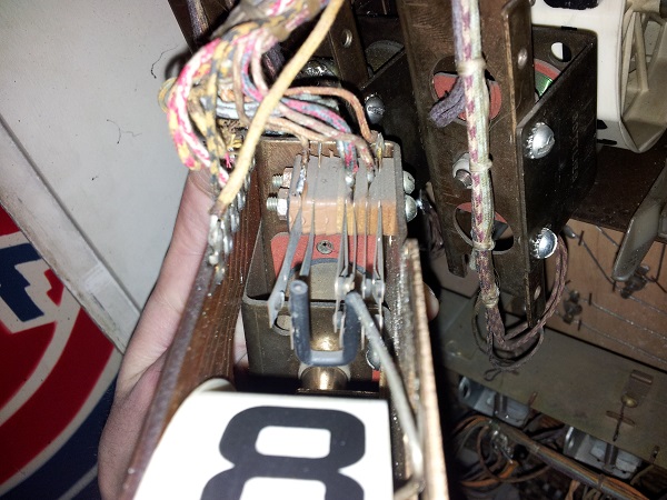
I decided to take a further look around the score reel – just out of curiosity. There is one other switch which is the EOS switch for the plunger (to advance the reel). This should always be closed until the plunger is pulled in. Correct adjustment here is also every important. No adjustment required though, it was working fine – but I understand that issues can and will arise from this switch not changing state correctly.
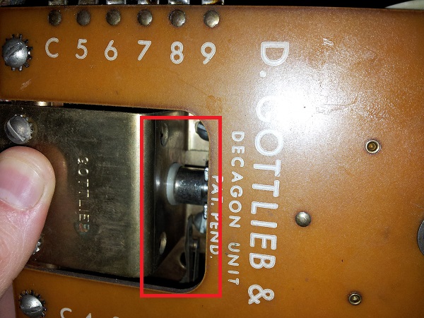
I didn’t bother to check the other score reels as they are correctly advancing and also carrying after 9th position – so it’s assumed they require no attention. With the 10,000 score reel 9th position switch correctly wired back up and adjusted (and the score reel put into its home again), I started a new game and advanced the score to 100,000 – this time, the lightbox advanced to 100,000.
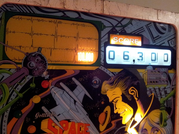
I kept going and watched it advance to 200,000 on the second rolling of the score. So that’s sorted out one of the 5 ball mode issues. The second issue is the amount of points awarded on WOW.
I swapped the position of the plug around through a few of the score values – 10,000, 20,000, 70,000, 80,000, etc. Each time 50,000 points would be awarded for hitting a lit WOW target. I then removed the score adjustment plug and tried again. Still 50,000 points were awarded (plus 5 pulses of the knocker). Curious, I switched back to add a ball mode and removed all score adjustment settings. I wanted to see if there was some “default” score level it used if none were set. But no, with no setting no free balls were awarded. I expected this, but wanted to confirm. Back to 5 ball mode then. So no matter what the setting (or no setting) – I get 50,000 points and 5 pulses of the knocker per lit target. OK, where to start on this one?
How about the score adjustment plugs – where do these lead to? Tracing the wires back, both the orange and green wires lead to a relay sitting in the headbox – next to the score reel relays. There are no markings on it (apart from a coil number), so I’m not sure what it’s identified as on the schematics. But both of these wires lead to a make / break switch at the base of this relay. I confirmed this by using my DMM on continuity and testing from the settings connectors to the switch tabs.
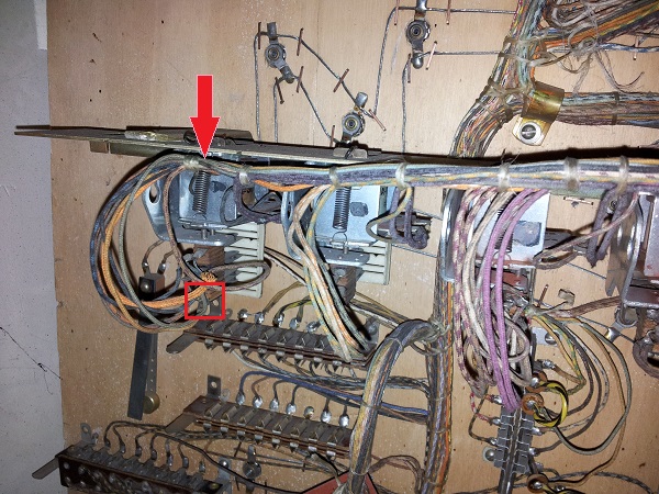
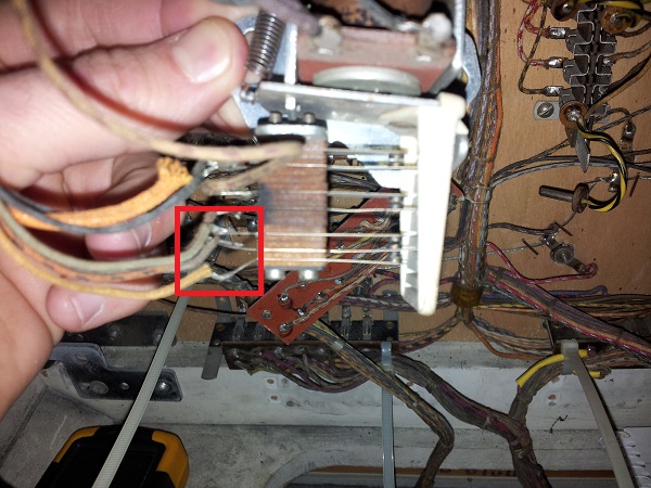
By default, with the coil not charged, the orange wire (add a ball score setting) is joined to the circuit and connected to the middle switch blade of the make/break switch. When this coil is pulsed, it will pull in and change state – at this point the green wire (5 ball score setting) will connect to complete the circuit. The next thing I wanted to know is – where does the wire on that middle switch blade lead to? I traced this back in the opposite direction and found it lead to the 4th lug on the add-a-ball mode jones plug.
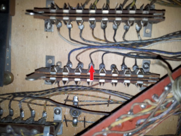
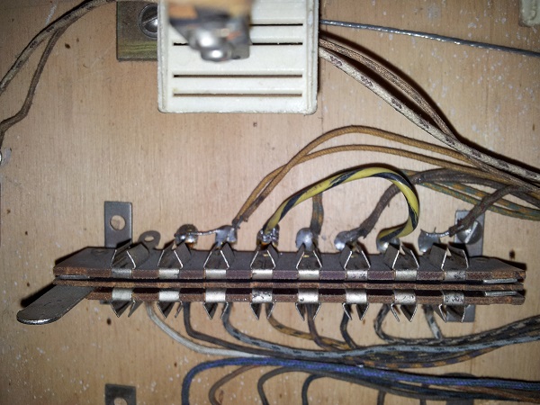
I tried the continuity test on all the wires connected to the 5 ball mode jones plug, but none of these were connected to that middle switch wire. There are quite a few wires on the 5 ball mode plug, some of which connect up two of the relays in the headbox (which must provide some sort of control over the awarding of points). I’m unsure about some of the wires here. The black and yellow wire runs from lug 4 to lug 7. There are two yellow wires connected to lug 2 – one comes from below (possibly from one of the other jones plugs) and the other heads up elsewhere in the headbox. There is also a small wire that runs between lugs 1 and 2. A few of the other lugs also have two wires running to them – these are all differences from the add a ball mode jones plug. I have no idea if this is correct or not, but looking at the other jones plug, these differences stand out as possible issues.
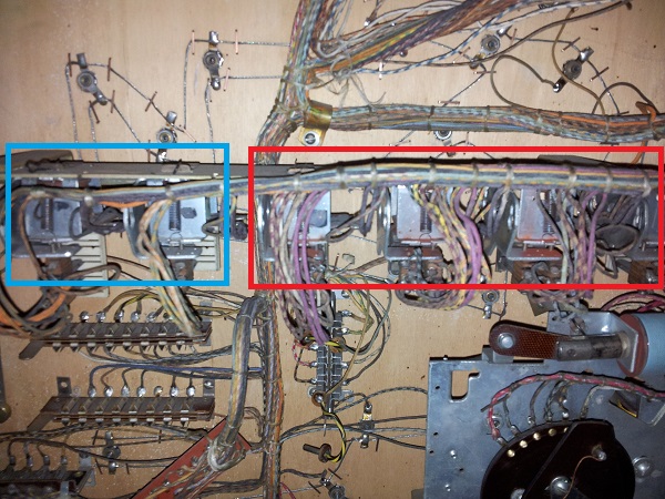
The relays that some of the wires off this jones plug connect to are located slightly higher up on in the headbox – The two in the blue box. The 4 relays in the red box control the 10, 100, 1000 and 10000 point score relays.
The next piece of information I wanted to know was where do the 10 wires from the score adjustment plug connect to? Turns out those are connected to the circuit board attached to the 10,000 point score reel. I buzzed each one with my DMM and mapped it to the score adjustment. These seemed reasonable enough.
I’ve gained quite a bit of knowledge over the last week from exploring the relays and switches. Examining the schematics and working out the above information. But at this point don’t feel much closer to understanding why 50,000 points are always awarded for WOW on 5 ball mode. A number of the wire colours on the schematics don’t line up with what I’m seeing either, which is making things difficult.
At this point I need to throw it out to the EM experts for help and advice on where or how to proceed with tracking this issue down. I suspect it’s something to do with that 5 ball jones plug. Given the make / break switch on the relay feeds back to the add a ball jones plug but not the 5 ball plug bolsters my suspicion. It’s also wired differently to the rest. Because add a ball works perfectly and awards balls at the scores specified, I believe that the majority of the machine must be running properly and shouldn’t require large fixes to wiring or switches. If there was a big issue, my expectation is I’d see it in add a ball mode too. It’s not too different in it’s operation – at set score levels, instead of awarding a free ball – should pulse the 10,000 relay (and knocker) a certain number of times). If any one has ideas, please let me know. Otherwise I’ll see what advice I can get from my EM friends and proceed from there.
