Having a set of pop bumpers on the playfield is almost mandatory for me when looking at pinball machines to play. The designers of Whirlwind must really have loved pop bumpers. Why have just one set on the playfield when you can have two? The only down side to pop bumpers is disassembling them as it cam be fiddly, especially those lamp sockets. The end result though after working on them really improves their performance, along with the presentation of a machine. It also makes them sound great too. The set I did in my previous update came up really nice and now it’s time to rebuild the second set. This update will be covering the final assemblies in the machine I need to look at, all of which are located at the top of the playfield. I’ll be starting first with the pop bumpers though.
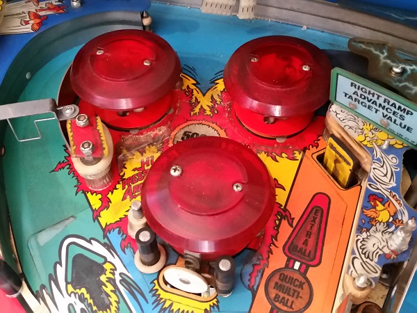
First step was to start removing things from the playfield. Plastics, posts and old rubbers came off first, revealing a dirty playfield. A number of the bulbs in this top playfield area are blown and will need to be replaced. One bulb in particular was really blown, with the glass exploding some time in the past. While there is a lot of dirt, there isn’t much playfield wear, which is great for a machine that’s seen a lot of action. It should all clean up well.
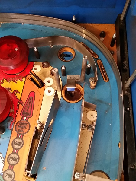
The left side of the playfield area was the same. You can actually make out where I’ve already partially cleaned some of the red area below where the ramp sits.
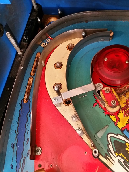
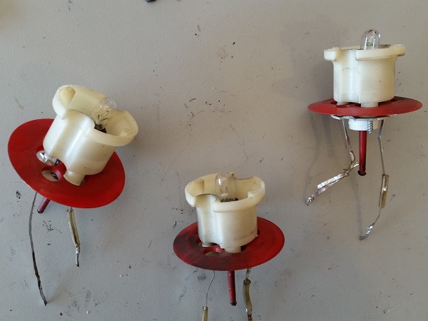
Now that I had most parts off the top area of the playfield, I got started on the pop bumpers. To begin with, I’ll remove the assemblies for each one. This then gives me easier access to the lamp socket legs to desolder and remove them. The set up is exactly the same as shown in my last update for the yellow pop bumper set and I’ll be following the same process.
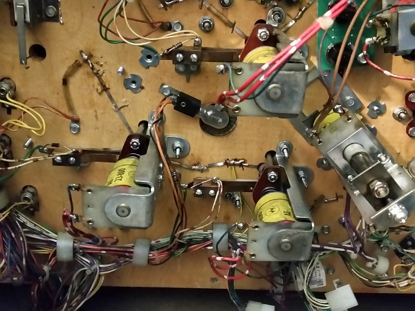
The pop bumper assembly parts were removed and set aside for cleaning. As with the previous set, these will go into the tumbler for a clean. No surprises were found here and no broken parts. After a clean they will be good to go again for awhile yet. The coil sleeves will be replaced though, but that’s always a given.
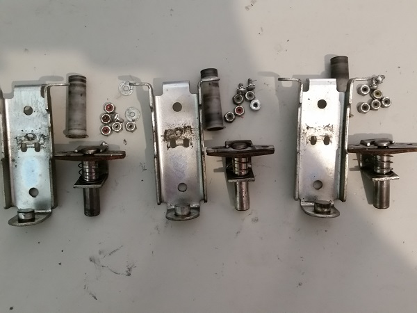
With the metal pieces from the pop bumper assemblies buzzing around in my tumbler, I continued on with the rest of the pop bumper parts. Top side, the caps were removed and I now had a clearer view on the state of the playfield in this area.
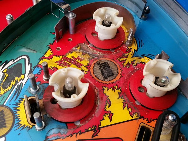
The lamp sockets were desoldered and the pop bumper bodies removed. A very dirty area on the playfield and quite a bit of lift from some parts of the mylar. There is also some wear around the edges of the pop bumpers where the mylar did not reach.
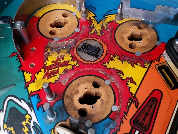
The area was given a good clean and then polish with Novus. The loose pieces of mylar which were flapping around were trimmed back and the dirt that had collected below was cleaned away. I didn’t want to remove all the mylar and only trimmed back the pieces that were loose. I also took the time now to remove a number of the metal ball guides and rails in the area to clean them. It made cleaning and polishing the playfield area easier too. Once done, they were installed back on to the playfield.
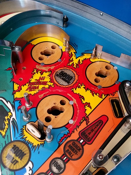
The old pop bumper bodies are looking old and tired. There is no point wasting time trying to clean them up. It’s cheap enough to replace the bodies and skirts. The lamp sockets on these wedge style ones were fine to reuse though, along with the base plastic and spring.
Before disassembling the pop bumpers I noticed how dirty the back panel was on the playfield. This really needed to be cleaned up.
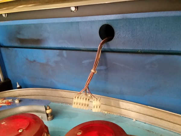
The back panel was cleaned up to make the blue look great again. The pop bumper bodies were rebuild with some new parts and installed back onto the playfield. New star posts were installed, along with new rubbers and cliffy post sleeves. I realised later (after taking a bunch of photos for this update) that I had the bell post rubber installed upside down. This has been fixed.
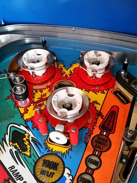
Finally the pop bumper caps were installed. One of the screws that was originally used on the old pop bumper caps was the wrong size. I had a dig through my spare parts though and found a replacement. The screws were cleaned up before installing too. The newly built pop bumpers where looking good.
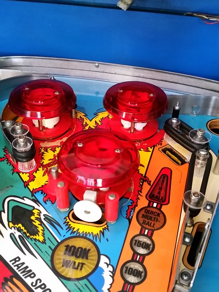
Time to power the machine on and test the pop bumpers to make sure all is well. I put the game into test mode and triggered each of the pop bumper switches. Everything worked correctly. I may adjust the spoon positions slightly, but will see how sensitive they are in testing first. Lit up they look great and now the top of the playfield is cleaning up nicely.
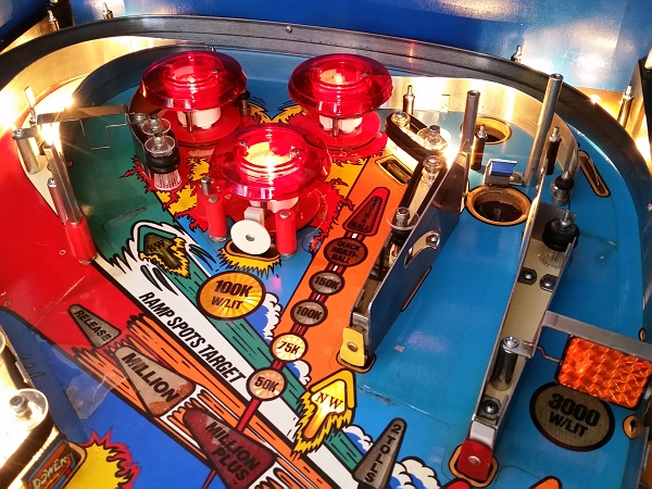
During the pop bumper rebuild, the left and right sides of the playfield in the area were also cleaned up. The left orbit lane was quite dirty to start with.
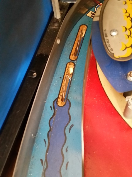
After some cleaning and polishing though, it makes a huge difference.
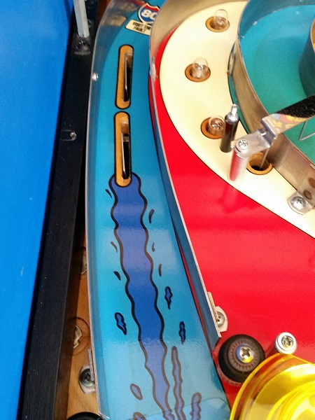
The next assembly to focus on is the single drop target that sits just to the right of the pop bumper assemblies.
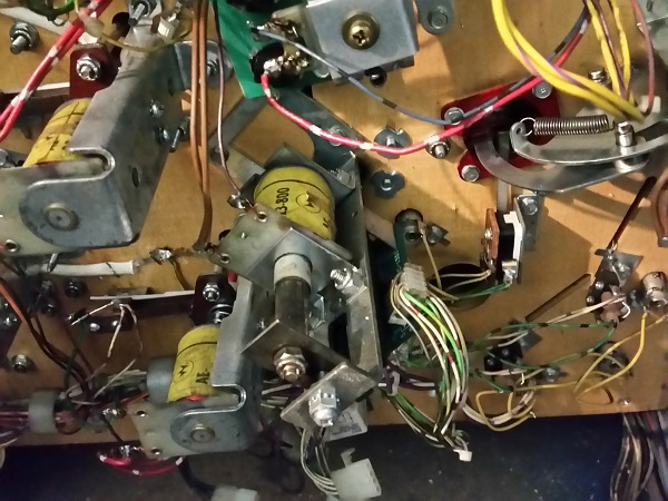
The drop target assembly was removed from the machine, ready to be stripped and cleaned. Construction wise, it’s the same design as the 3 bank – only one third the size.
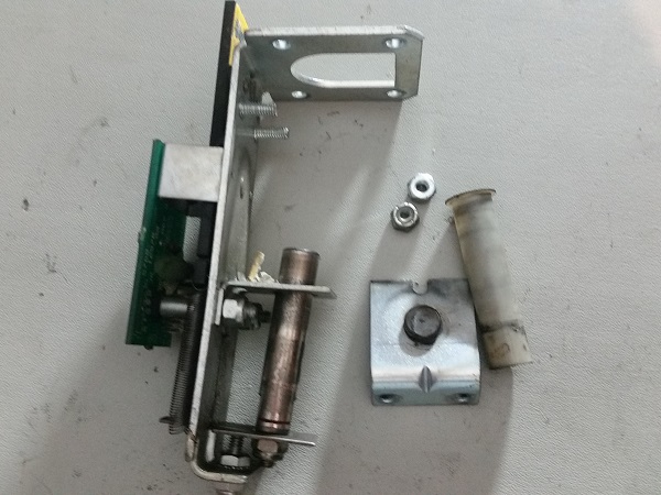
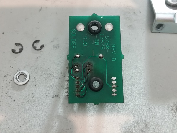
While pulling the drop target apart, I noticed there were some hacks on the rear side of the PCB. The target opto works fine in game, so I won’t be changing this. I’m mainly documenting it for the owner so he’s aware of it should any problems arise with the target in the future. You can buy replacement boards from Marco for these single drop target banks, for around $35AU.
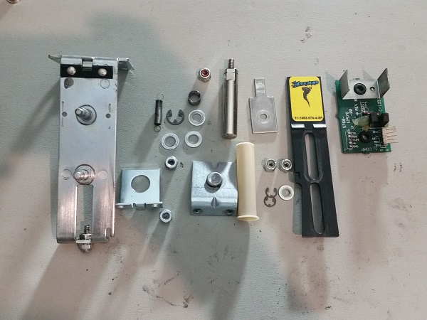
The drop target assembly was disassembled into it’s individual components and each one cleaned up. The old coil sleeve was replaced with a new one. The drop target decal was replaced with one from the new set (shown in the previous update).
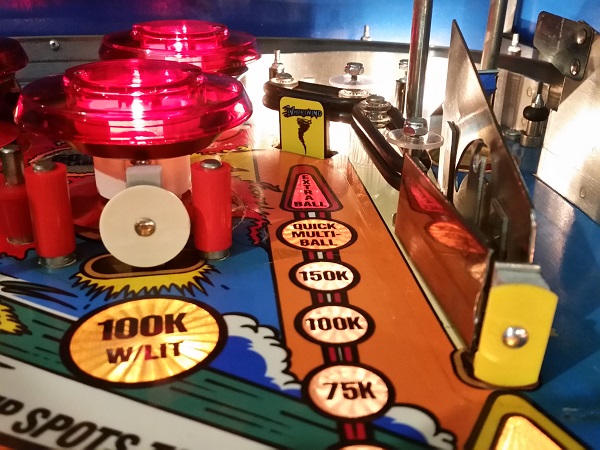
The drop target assembly was rebuilt and installed back into the machine. It operates much more smoothly and looks nicer with the fresh decal.
Something I skipped in my previous update was cleaning up the spinner discs. They are all part of the one large assembly. The underside of the frame is really filthy. I want to get rid of any loose crap, along with the surface layer to clean it up. I had asked the owner when he dropped the machine off about replacing the spinner decals since they are available. At the time he was keen to keep the originals. That’s now changed, so new decals have been ordered and will be applied in the next update. As a note – if you buy new spinner decals for your machine, make sure you’re getting the textured ones. Without the texture, it won’t grab the ball and fling it in all directions.
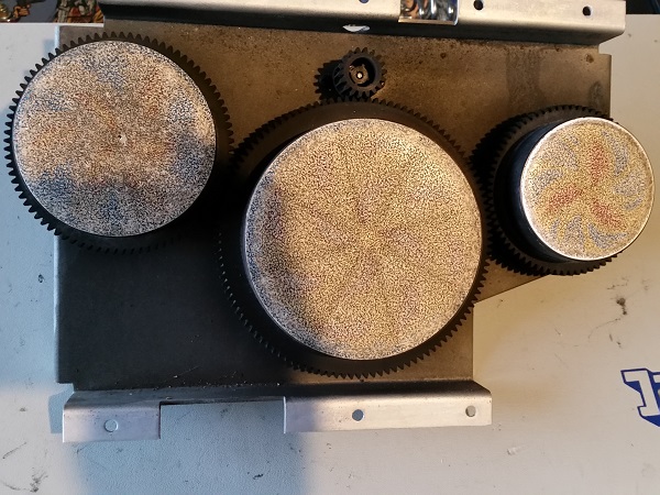
The holes below the spinners were quite filthy and I wanted to clean this up too.
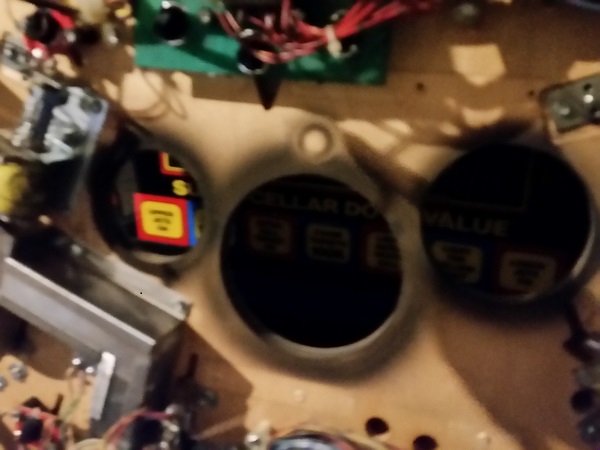
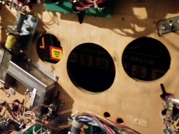
The area around the disc holes was cleaned up, ready for the spinners to be installed back into the machine. The spinner decals should arrive sometime late next week and will hopefully appear in the next update 🙂
Not many assemblies to look at now. The next one is the saucer. It’s not much different to the ball serve assembly. This one sits hidden away (usually) by the right ramp. When you trigger the ramp to lift during game play, you then get access to this. It then kicks the ball back out to the right orbit lane. You can spot a few small wear marks where the ball has been kicked out into the lane. I may put a small mylar patch over these to prevent further wear.
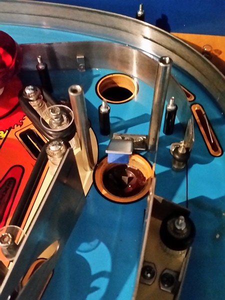
Under the playfield, the make up of the assembly is the same as the ball serve. An arm to kick the ball out with a plunger that’s pulled in from a coil. I’ll also want to remove the red saucer shield to give it a clean.
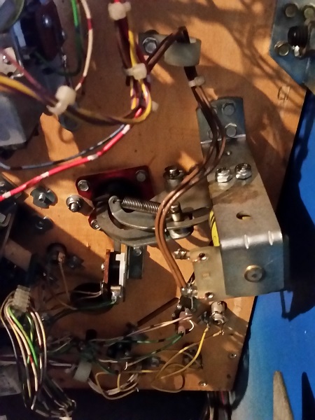
The parts were removed, ready to receive some attention. No nasty surprises here, just some filth to clean off. If anything, I’m surprised the red shield is still in one piece. Often they break from years of use and the ball slamming into it.
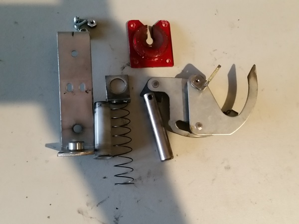
The assembly was broken down in to its components and everything cleaned before being put back into the game.
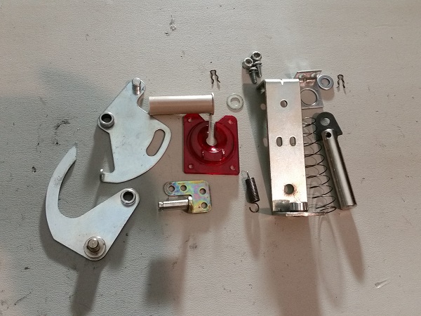
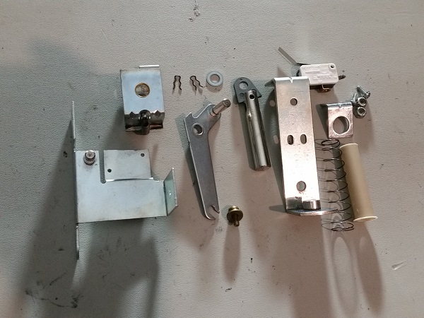
The final assembly to look at is the one used to raise and lower the right ramp. It’s the same style as I serviced on my Pinbot. The parts were removed from the machine for cleaning.
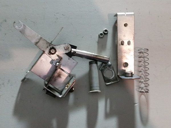
As with all the other assemblies, it was disassembled into it’s pieces and each one cleaned. A new coil sleeve will replace the old one.
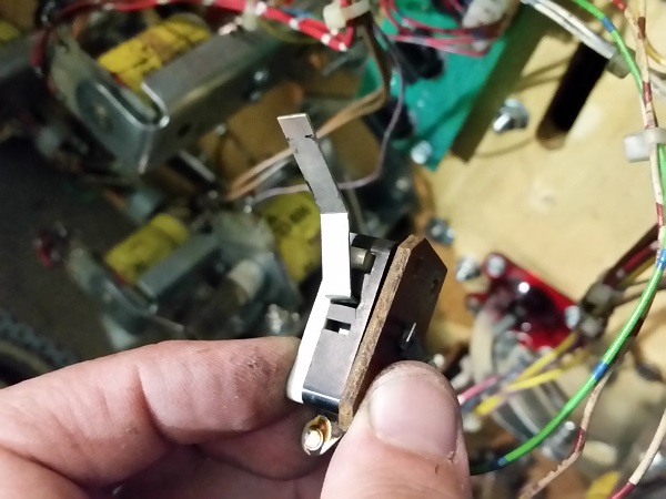
Although I had fixed the ramp assembly (back in update #1), I was concerned about the state of the switch now that I could see it close up. The switch blade was quite loose and a crack had formed in the switch plastic around it. I have no doubt this is because of how the assembly arm had been sitting on the wrong side of that switch. Every time the game told the ramp to rise, the assembly arm would bash against the underside of the switch blade. Repeat that enough times and damage will start to form. I did purchase a spare one weeks ago, so have decided to go ahead and install it so the owner can have confidence that the ramp assembly will function correctly well in to the future.
The ramp assembly was installed back into the machine, marking off the final assembly I wanted to look at on the game. I decided to fire the game up and take a few photos to show the current progress. It’s already come a long way and cleaned up nicely. I still have plastics to go back on, along with the ramps too.
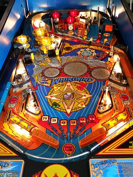
There are clear lexan washers on the corners for each plastic to help prevent future damage to the new and existing plastics. I always love looking at photos like this and comparing to my start photos to see how much a difference the cleaning and serving really makes.
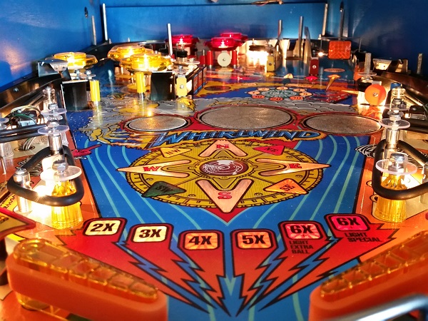
I’m not complete yet though, so no time to stop. Next step is to clean up the good plastics and install them again. The 4 new plastic pieces arrived today, which will also be installed too as part of the next update. I need to clean the ramps up, which I’m looking forward to as they are filthy. The coin door is still on my to do list as well. There are fewer things to do now, so getting towards the end of my work on the machine. I’m looking forward to getting a few ‘test’ games in once complete!
