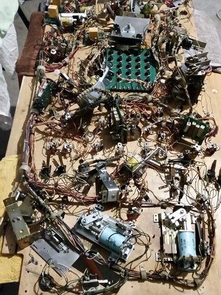
The Pinbot playfield swap continues to move forward, with bits and pieces done each day. Following on from my previous update, the first task to report on is getting everything on the old playfield ready to dump/move/slide/transfer across to the new one. This involves removing all screws, so anything attached to the underside of the playfield is free to be moved. It also means the removal of all staples holding the GI sockets to the playfield and the ground braid that runs between them. There are a few instances where wires had been soldered to lamp socket screws, which means they will need to be desoldered first so I can remove the screw. I started at the base of the playfield and slowly worked my way up to the top. Eventually I had worked my way up the entire playfield, leaving nothing attached to the surface. It just looks like a big mess.
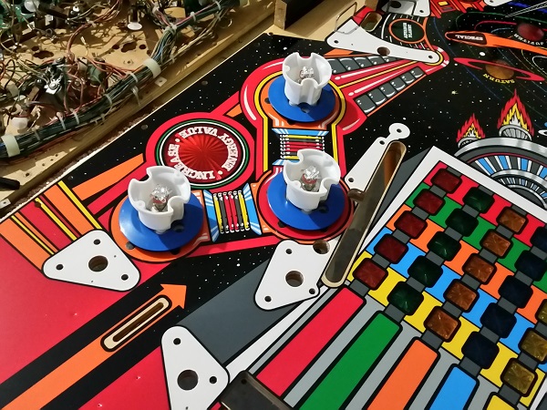
Before I transfer all the parts, I wanted to get the pop bumper bodies installed and their lamp socket legs in position ready to be soldered. This will also ensure I can line up the spoons in the correct position when putting the parts onto the new playfield. The 3 pop bumper bodies were installed on top of the playfield. These use all new parts (as covered in an earlier update from awhile back), so look nice on the new playfield. I have also added LEDs, replacing the incandescent bulbs. These ones have 4 smaller leds and 1 high power pointing up. I liked how they looked when installed on my LAH pop bumpers, so decided to go with them again here.
The playfield was then flipped back over again, ready to receive all the parts from the old playfield. I slid a sheet of cardboard under the parts on the old playfield and then lifted them across to the new one. This left the old playfield showing it’s scars and filth from its many years of faithful service. Time to retire, my friend.
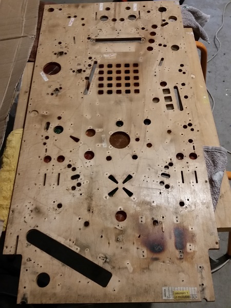
On the art side, there is some wear in various places and a small amount of planking around the ball drain area. There’s a number of inserts on the chest matrix that are slightly raised, along with the red special insert. I plan to fix the inserts of the chest matrix at a later date. For now though, I will keep the playfield handy so I can use the screw holes as a reference and comparison with the new playfield as the parts are installed.
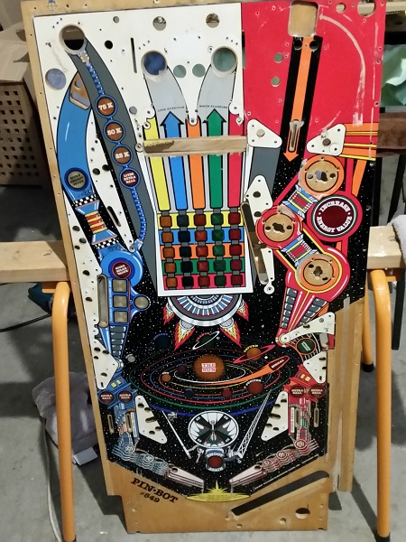
Meanwhile, on the new playfield, a scattered mess of parts await installation into their new home positions.
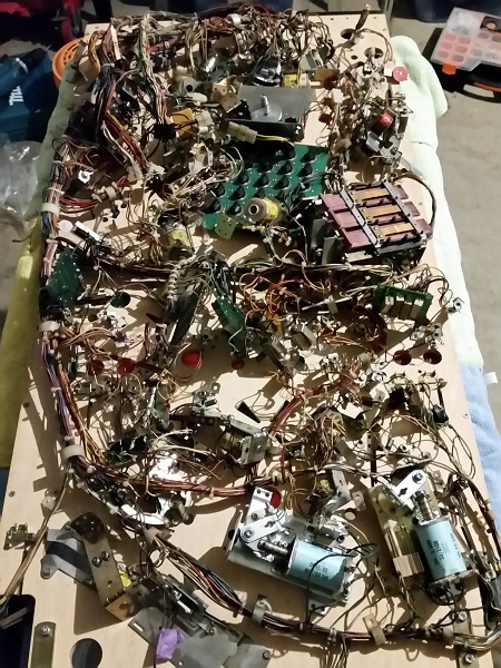
Where to begin? Something I had to keep at the forefront of my mind is installing the ground braid, as this requires staples. Getting this done earlier before too many parts are installed makes sense, since it should be easier to access the areas required with the air stapler. It would be good to get a few things installed first though to clear some of the area where the ground braid needs to be installed. So, I decided to start installing parts from the base of the playfield (ball trough, ball serve, flippers, etc) and work my way up to the lower 2 sections of ground braid.
Slowly but surely, I got the components in the lower area of the playfield installed. This includes the ball trough, ball serve, flippers, sling shots, in/out lanes and some of the insert lamps. There are two areas here where the ground braid required installation and this was done next as the areas had been cleared up a bit. The lower section was coming together nicely. Installing the lamp sockets was quite easy as their position isn’t as strict as the assemblies. I found a number of dimples missing for the assemblies around the ball trough, so used the old playfield and already installed components as reference to get the alignment right. The supplied dimples are only to be taken as a guide anyway (as per CPR’s install guide), so I’ve been taking my time to get things lined up properly. I continued to work up the playfield, getting the lamps installed for the planet inserts and some more of the PCB’s. I was now about half way up the playfield. The underside of the playfield is coming together nicely and is noticeably better than the previous photo.
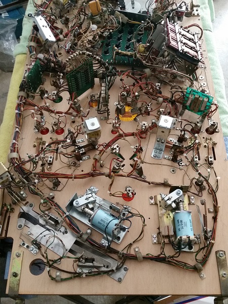
I continued to work up the playfield. The drop target bank and its inserts were done next, followed by the ramp arm assembly. The last few planet insert lamps were installed and then the chest matrix lamp board. I wanted to get a few more things done around the pop bumpers to clear out space, creating room to install the ground braid that runs around the pop bumpers and playfield GI. Eventually I reached the top and the underside of the playfield was now back together again.
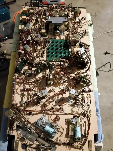
Along the way I found a few cases where wires had become detached from their solder joints during the transition to the new playfield. Each was soldered back into its correct home.
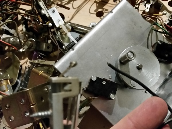
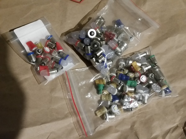
I took this opportunity to check the solder on each wire, making sure all were sitting correctly. I also grabbed some extra zip ties and tidied up the wire a little bit more. Before flipping the playfield over, I had ordered a pile of LEDs for the inserts. These were installed.
That’s it for update #3 in the playfield swap. The underside is now complete and I’m ready to begin getting the top of the playfield back together again. I may need to return to the underside if I find the position of some assemblies need adjusting, but I won’t know for sure until it’s in the machine an in a testable state. It’s great to see the playfield coming together now and the end result should be worth all the effort.

Can you go into detail about what bulbs you used where and why? Also, where you ordered them from?
I used the frosted style for GI lighting – with blue on the left and red on the right. For the inserts I colour matched to the insert and used super bright. The LEDs were purchased from a local pinball supplier. My preference are the premium style from Pinball Life as they eliminate ghosting on the CPU controlled LEDs. There are probably other LEDs that have the same effect too. I stuck with #89 flasher bulbs though as if you switch to LED flashers on this game (and some other Williams games), the flasher will always be on due to how the game is constantly running current to the bulb. It’s not enough to light up a globe, but enough for a LED to be on. You can eliminate this with a mod to the flasher boards, but I decided against it.