I’ve been conveniently putting this off for awhile now, but time to get some connectors repinned. Earlier posts for this project showed two lovely hack jobs on some connectors. The first appears on the J8 connectors on the power supply board.
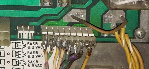
This thing looks horrible. Still, it works and that’s been good enough for now. But time to make it right. I ordered two new 9 pin IDC connectors, along with two 9 pin male connectors so I could replace them on the PCBs.
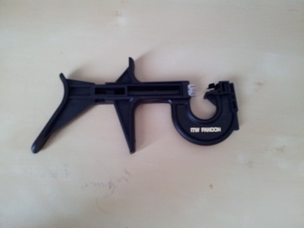
I also purchased a tool to make the job easier. A bit pricey (roughly $95AU), but it’s well worth it. It made the job effortless and completed within 5 minutes.
One by one, I clipped the wires from the old connector and installed them onto the new connector. Thankfully there was enough length in the wire without the need to extend it. This is looking much nicer now.
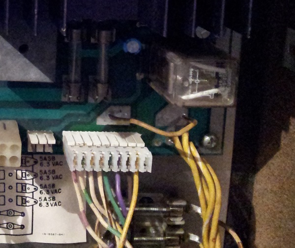
At that point I removed the power board to replace the male connector. I then noticed something odd. The wires connect to pins 2 to 9. But pin 5 is the key pin. Why does pin 5 have a wire connected to it and pin 1 not? Off to the manual.
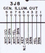
Here I could see that pins 6 to 9 were correctly wired up based on the wire colours. Pin 5 was indeed a key pin, so should have nothing installed. The green wire that was currently connected to pin 5 should be pin 3. The brown wire in pin 3 should be in pin 1. Digging further into the manual I found these 4 wires lead off to some of the flashers. Looking at the back of the PCB, pins 1 to 4 are all joined together and pins 6 to 9 are joined together. I shifted the green and brown wires into their correct place.
At that point I replaced the male connector on the PCB and installed it back into the machine. This process was more time consuming and really highlighted my need for a proper desoldering station.
Now onto the connector on the cpu board. This started out with two wires soldered directly to the male pins. These two wires are ground wires for the flippers. Given the flipper coil damage I had seen earlier under the playfield, I wasn’t surprised to learn these were related. I had attached a 2 pin connected in the short term to make it easy to remove the CPU board when needed. But again, time to fix it right.
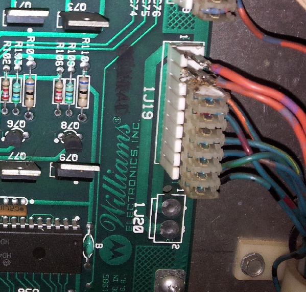
Similar story, each wire was removed one by one and transferred to the new connector. The tool really came in handy here and I don’t regret splashing out on it.
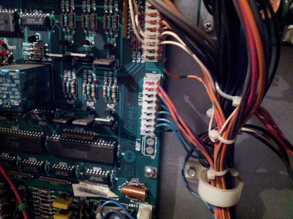
The male connector on the cpu board was also replaced. At this point I fired the machine up and put the game into test mode. I found everything worked except for the lower pop bumper. The coil tested OK and the switch was working. Looking at the manual I found the solenoid wire was part of the connector I just replaced. Looking at the connector I could see the wire was not quite pushed in enough. I got the tool out and pushed it all the way in. Retested and now working.
I had put this off for so long, but really, it turned out to be quite straight forward (with the right tools 😉 )
