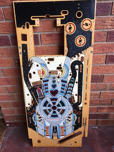
Who likes self punishment? I do, it seems. My BoP 2.0 machine came with a touched up and clear coated playfield when I purchased it 14 months ago and it’s a task I knew I would get to at some point. But when you’re having fun playing a game, it’s hard to take it offline for some major changes. Playfield swaps are a time consuming process, so it’s not something I’ve been looking forward to. I gained some excellent experience when I did my Pinbot CPR playfield a couple of years ago and I’ll be rolling that knowledge in to how I approach this one. The up side here is the replacement playfield is an existing playfield, so all screw holes (both sides) are already there. New playfields have (most) screw holes dimpled, but can be up to 1mm out in any direction (according to CPR – not sure if that also applies to other playfield makers). On my Pinbot playfield, I found many dimples missing on the underside. This can be a pain for assemblies under the playfield that are made up of 2 or 3 components, consisting of up to 12 screws, which all need to line up in order for it to operate smoothly. The current playfield in my game isn’t bad by any stretch as mylar across the central playfield and pop bumper areas has protected most of it. I actually think it would make a great drop in replacement for someone who has a trashed playfield or someone who wants to touch up and clear coat one for themselves. Time to begin the process.
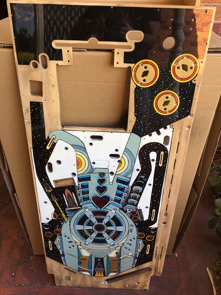
First step is to take a series of photos of the playfield from many angles. Having done a lot of work on my BoP already, I’m pretty familiar with how the playfield should be and where things go. But my memory isn’t photographic and if I’m putting things back and something isn’t quite right, the photos come to the rescue. Something I learnt last time was to take more photos that you think you’ll need – better to have too many reference photos than not enough!
Stripping the top of the playfield is the next step. I again take a lot of photos during the process and I group parts in to bags to make reassembly easier. For example there will be a bag for the left sling shot parts and separate bag for the right sling shot parts. This is repeated all the way up the playfield and things are grouped to make it obvious where they go. It also helps ensure parts don’t get mixed up or go missing as the bags are sealed.
Where there are similar parts like metal posts, some of which are similar sizes, I tag them with numbers, take a photo and then remove them. This helps ensure the correct posts go back in to the correct spots. I use this with the pop bumpers too as this means I get lamp wiring back in the correct way.
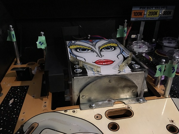
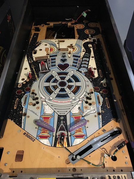
I continued to remove the remaining parts on top of the playfield until everything (except the flippers) were off. The top of the playfield was now stripped and it was ready to be removed. This makes the playfield a lot lighter and easier to get out of the cabinet. The stand up targets and sling shot parts that stick above the playfield will be undone from below in the next phase of the swap.
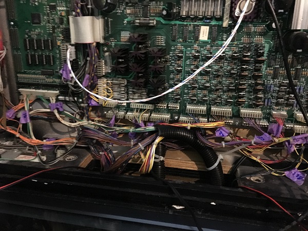
Before I remove the playfield though, I tag all the connectors in the headbox so I know exactly what board and position they go back in to. Photos are also taken of the boards before the tagging is done, so I can clearly see which connectors go where.
The parts from the top of the playfield were set aside in two boxes and put in to a safe place, ready for rebuilding shortly.
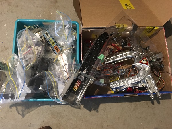
With the playfield ready to be removed, I next need to do some prep work on the replacement playfield. Whoever clear coated the playfield decided to leave the pop bumper shanks in. This isn’t a bad idea.
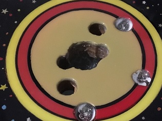
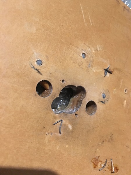
…Except when they decide to cut off the tips of the shanks. There are two approaches here that would have been far better. Leave the pop bumper shanks in as is and clear over the tops. The down side to that is you have 9 shanks exposed while transporting the playfield. Or secondly, remove them and apply the clear. It’s much easier (and safer) to use a brad tipped drill piece to scrap away the clear around the hold edge before installing the shanks again, then having to carefully pick away at the clear around the screws here and then remove what’s left. Using a needle tipped scraping tool (not sure what the correct term for it is), the clear over the heads was carefully removed so the old shanks could be removed and those from my original playfield installed in their place. The staple and pop bumper lamp leg remnants were removed also.
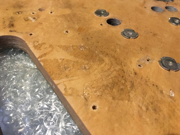
Across several areas of the underside of the clear coated playfield were sticky patches, probably from some sort of tape. I wanted to clean this away before transferring the parts across. Eucalyptus oil was used to clear away the residue.
A number of the inserts had a white substance across the underside of them.
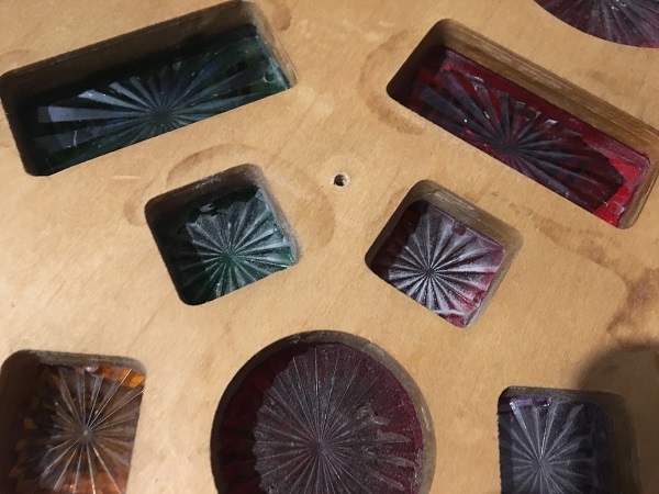
This was cleaned up to get the inserts clear, allowing as much light through from the LED’s as possible.
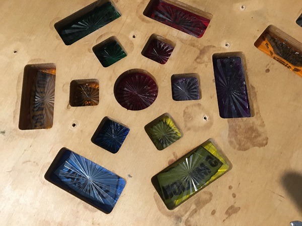
The old playfield was removed from the cabinet and set down, ready to have all screws removed from the underside so parts could be transferred to the new playfield. I don’t have a rotisserie, which would make the next couple of phases much easier. Some saw horses will have to do. At this point I took another series of photos all the way up the playfield and from different angles. These will be used as reference when screwing everything back in to place on the new playfield. Because I’m transferring to an existing playfield, many things will be obvious as to where they go. That makes the reassembly task easier than going to a brand new playfield.
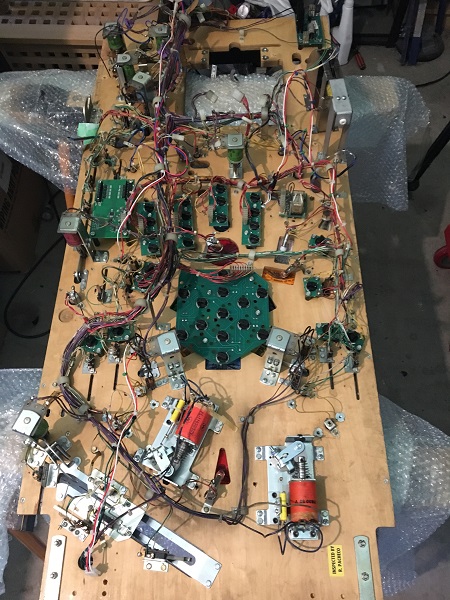
I split the playfield up in to 3 sections: lower, middle and top. As I work my way up, I undo all the screws in a section, take more photos so I can clearly see which screws go where and then bag them up separately. The plan here is I can then take the screw bag for the lower section and reassemble the parts. Before moving to the next section, I should have no remaining screws and everything in that section should be screwed back in place. There are two different length screws used and it’s important to make sure they go back in the correct spot. You don’t want to use a long screw where a short one is required and find you end up with damage on the top side. After all three sections are complete, a tangled mess is left and ready to transfer across.
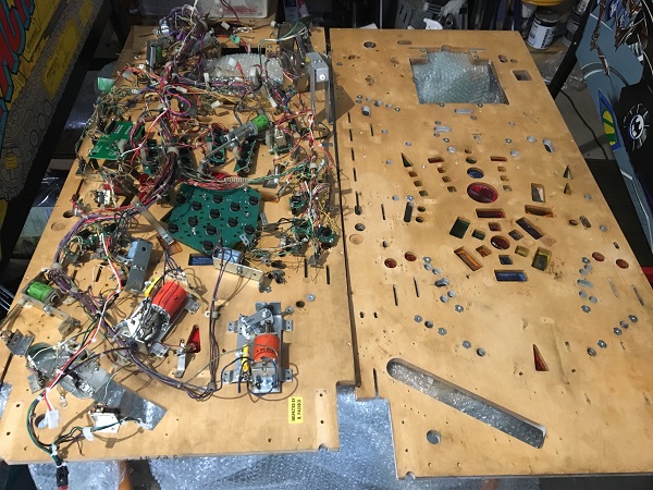
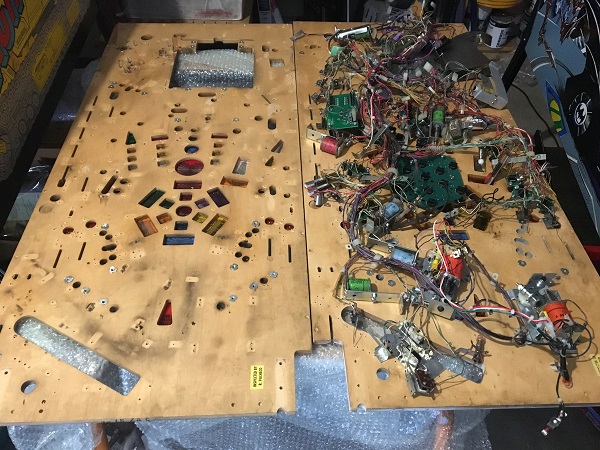
I grabbed a large cardboad box from Bunnings and cut it into shape to fit the length and width of the playfield. All parts from the old playfield were lifted and the cardboard slid under until everything was resting on top of the cardboard sheet. I could then just slide the cardboard across to the new playfield in one motion. Finally the cardboard is carefully removed, leaving the parts transferred, roughly in the spots they need to go.
The rear panel of the playfield had been removed and before I install it again, I want to give it a fresh coat of gloss black.
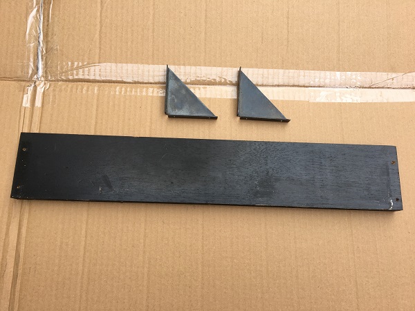
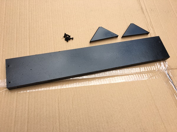
After a clean and two coats of gloss black, the brackets, screws and rear panel were looking nicer and ready to go.
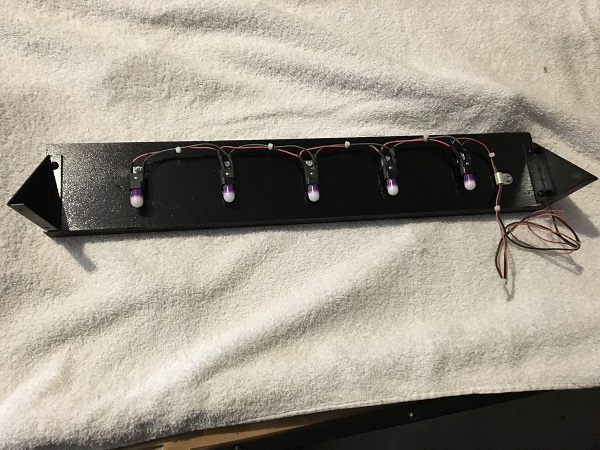
A small mod I made to my machine awhile back was to install two small LED strips on the rear panel. I was never really happy with the result of them, as they were too bright. For GI, I much prefer the frosted dome LED’s and decided to replace the strips with a series of #555’s along the rear panel. I can then angle these as desired.
Back to the playfield, I slowly chipped away at screwing everything back in to place. All the reference photos came in handy here and I’m glad I took extra shots from multiple angles as you can easily miss things with just a single shot. As mentioned earlier, the playfield had been split in to 3 sections: lower, middle and top. I started with the lower section and used the labeled screw pack. Once complete, I moved to the middle and then finally the top. This was a good way to ensure the correct screws went in to the correct locations and none were missed. It’s always a good feeling to have nothing left over and everything attached at the end 🙂
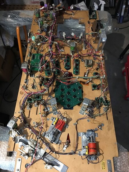
The playfield was flipped over and I began the process of installing parts again. Because the parts bags were grouped and labelled, it made installing them straight forward. I started with the pop bumpers, posts, trough and several ball guides. A brad tipped drill piece was used to scrape away some of the clear around the screw holes before screwing parts back in. This is the phase where a rotisserie really would make the job easier, but I’ll get through it. Hard to justify buying / making one that’s used once every 2 years.
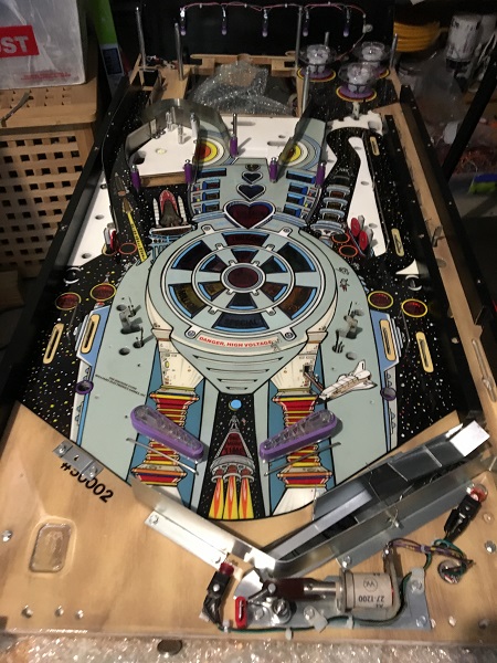
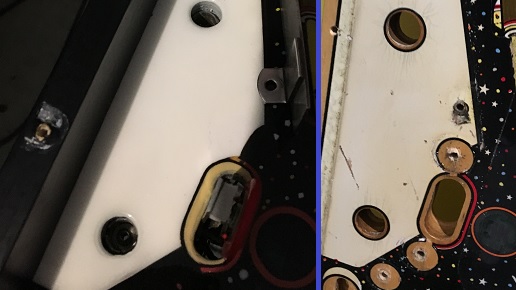
One of the challenges I faced with this playfield is that while many of the screw holes were still obvious and only needed some of the clear coat removed (using the brad tipped drill bits), there were holes that had been completely covered. In this section on the left, 4 holes were no longer visible. By rubbing my finger over the area, I managed to find very small traces of where the holes once were and they were carefully drilled. This also applied to several spots where wire forms are installed into the playfield (return lanes for example). The holes here had been completely filled in. Thankfully those holes go all the way through the playfield, so I could find their correct location from under the playfield, and these had to be carefully drilled from the bottom up first, and then a brad tipped piece used to remove some of the clear for the wire form to be installed. I don’t understand why this was done, but it’s just one of the unique challenges you face while doing this sort of thing.
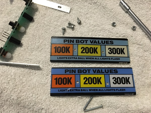
When I purchased the CPR plastic set 12 months ago, I never got around to replacing the PinBot values sign at the rear of the playfield. It’s a pain to remove on its own, so I left it until it was time to do the playfield swap. That time has come. The original one looks fine and you don’t really notice the colour improvement until you have both old and new side by side. Then it becomes clear how nice the new one looks!
Bit by bit, I worked my way through the tub of parts bags, getting the playfield back together. The return lanes and sling shots were installed, along with more ball rails, posts and rubbers.
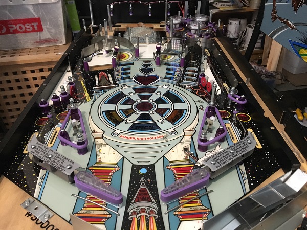
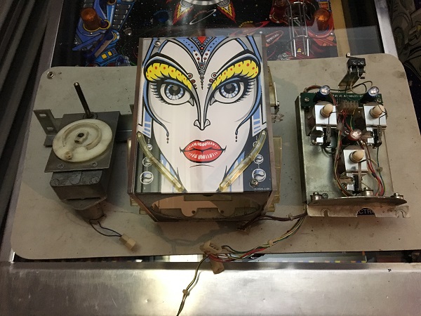
The brides head is made up of 3 parts: the motor, the face box and the assembly plate. The switches needed a small adjustment before putting the head back into the playfield.
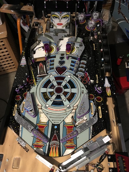
The brides head was installed back into the playfield, along with the skill shot parts and many of the plastics. The playfield was now starting to take shape again.
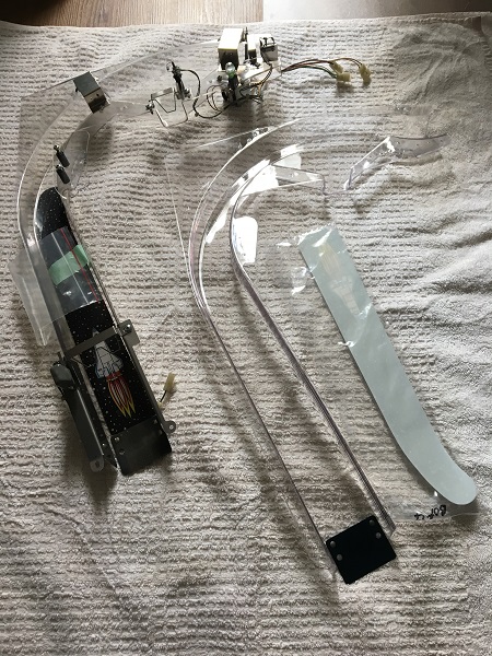
Another part I purchased awhile back, but didn’t get in time for my previous work on the game was a new shuttle ramp from RTBB. This is the perfect time to get the new ramp in. I’ll disassemble the old ramp and transfer the parts across to the new one. The old ramp isn’t in terrible condition, but does have some damage around the entry. A cliffy set I purchased worked wonders for it, but since I had replaced the heart beat ramp, I was keen to replace this one too. With all the work put in to the machine, it felt like a disservice to not replace this ramp.
In one of my parts orders many months ago, I included a new plastic housing for the ball lock. The old one isn’t terrible, but cleaner plastic and fresh decals add some subtle improvement that probably only I care about 😉
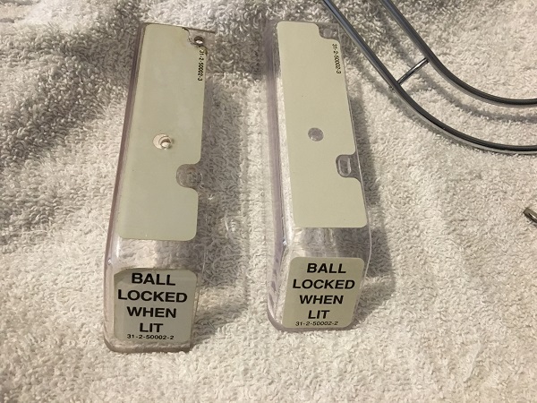
The ramps were installed back on to the playfield, along with the mini playfield, rails and helmet. Doing all this with the playfield out of the cabinet made things easier, especially around the face and helmet area as feeding the connectors through while the playfield is in the cabinet can painful and the ultimate endurance test in patience. As I went, the vacuum was used to suck up lose dust and surfaces were wiped down to have the playfield as clean as possible. While not working on it, I left the playfield covered. Finally, the playfield was back together again. No spare screws or parts – if this was an Xbox / Playstation game, there would be a gold medal achievement unlocked for this feat 😉 I also added a few small mylar patches where the ball can drop – directly below the mini playfield and also in each return lane. A metal ball against clear coat – the ball will win – so this should add some protection.
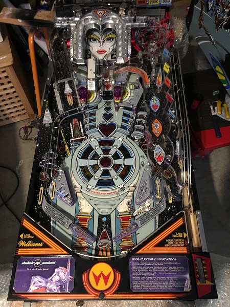
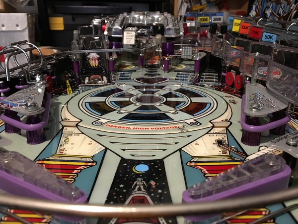
Before putting the playfield back in to the cabinet, I wanted to spend 20 minutes tidying up the wiring a bit. One issue I get every time I lift the playfield is the white power board always gets in the way. The power board is part of the BoP 2.0 kit, and is used to provide power to the Amp, LCD display and computer. After untangling the cables and wires, everything was organised to keep the power board at the back, away from the rear of the playfield.
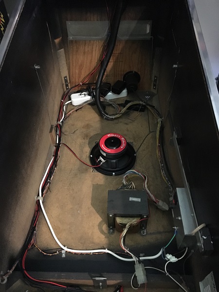
One last step before installing the playfield back into the cabinet was to tie some rope to the cables, which will make feeding them up to the headbox simple.
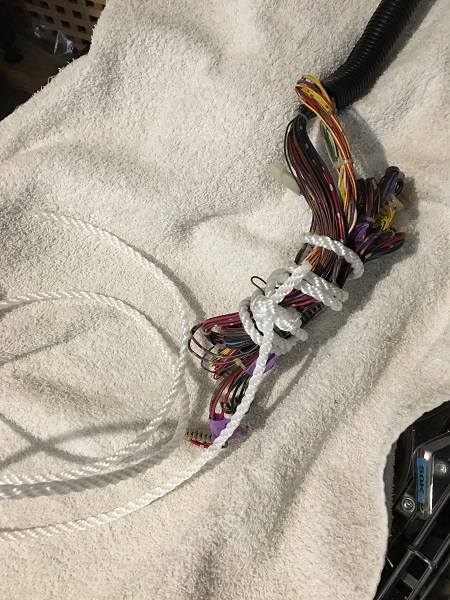
The playfield was installed back into the cabinet. It’s a lot heavier with all the parts attached and more awkward to get back in. So while keeping it out made reassembly easier, that made getting it back in tougher. So a bit of a trade off – but I think I went the correct path. The connectors were installed again in the headbox and the machine was now ready to power on. Now for some testing.
A playfield swap is obviously very invasive to the machine, so there are always likely to be a few issues to sort out. The first issue I found before even switching the machine on. There is a small one way gate on the ramp that runs between the out hole and ball trough. I installed the gate in the wrong direction, so no balls could be fed through to the trough. I removed the apron to swap it around to how it should be. From there I booted the game up and found the display not working. This was due to the power connector not sitting right on the display. Once the game booted I observed the CPU controlled lights and found all were working. I then printed off the switch matrix and coil list and entered test mode to ensure everything was working.
I found that I had installed the left and right pop bumper coils in the wrong assemblies. The easiest fix here was to simply get the soldering iron out and swap the wires over. It’s much less hassle then removing two pop bumper assemblies to get the coils corrected. All other coils fired correctly.
I found a switch on the shuttle ramp not working quite right – the head entry switch. This just needed some adjustment as the switch itself did register, but it was not sensitive enough when the ball passed through it. The two right lane switches registered fine when activated with my finger, but not when the ball passed over them. This was a simple adjustment also. That was the last issues to resolve. The game was now ready to play.
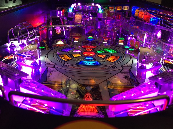
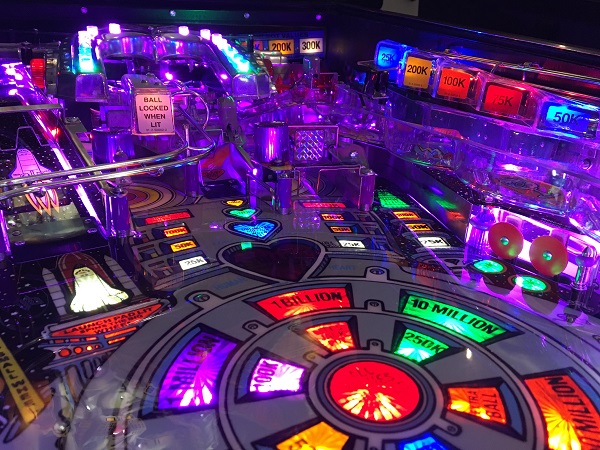
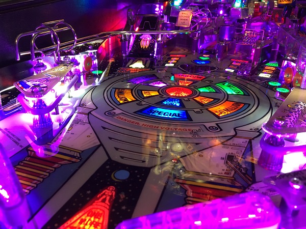
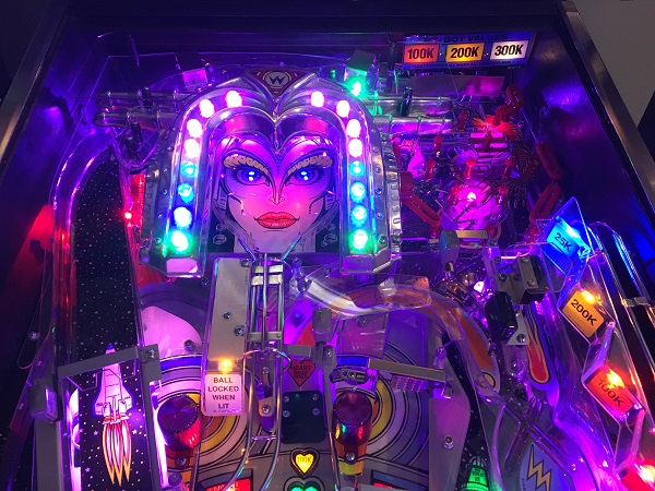
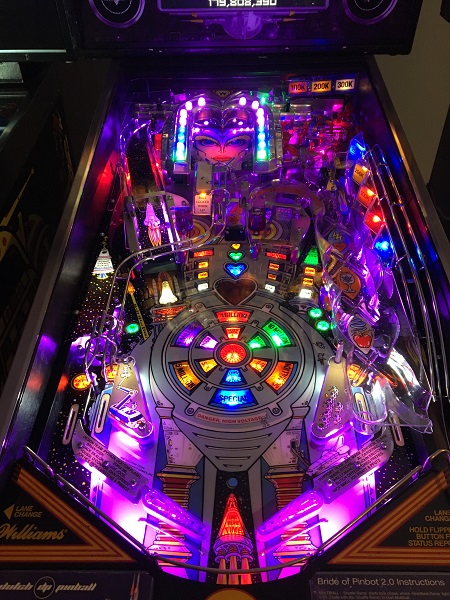
The old playfield has done a fine job and held up well over the years (it’s now 28 years old!).
The BoP playfield swap was now complete. I played several games, observing behavior to see if any additional issues presented themselves. So far, the only thing I will do is adjust the position of the left return wire form as it’s not quite central to the return lane. Otherwise, the game is holding up great so far. It plays differently now with the clear coated playfield and will take some adjusting. But it plays nicely, which is all important and makes all the work worth it!
There were some further valuable lessons learned here that I can use to improve the process next time I decide to do a playfield swap. However, I feel as I did after my Pinbot playfield swap – I won’t be rushing in to do another any time soon. It’s a slow stop / start process, which I spread it out across a couple of weeks, allowing me to take my time. All up I would have spent close to 45 hours from the moment I started to the moment it was ready to play. I’m not quite done on my BoP just yet though, as there is one more task to complete on my beloved machine. New cabinet decals. This had been planned as a Christmas holidays project for me, but a hold up on the decal delivery looks like it will be pushed back until late January / early February. So there are still a couple more posts left for me to do on this machine – stay tuned 🙂
