There was a time where I would have weeks (often months) between pinball projects. Not any more though. As one machine goes out the door, the next one rolls right on in. This time it’s back-to-back SEGA’s with a Harley Davidson replacing the Apollo 13. The last SEGA game before Stern took over. It was released in 1999 and there ended up being 3 editions released. The first from SEGA, which Stern then continued once it took over. That was followed by 2 additional editions a few years later by Stern. The game powers up, but has a few issues to look at. It needs a really good clean, but that’s typical of most games that come my way. The main issue I’m concerned about is (seemingly) random resets, which I will get to shortly. It has some mechanical issues, but those won’t be a problem to sort out. Let’s get started!
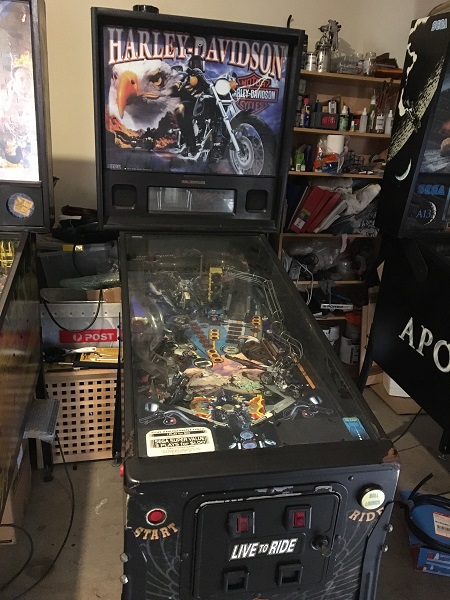
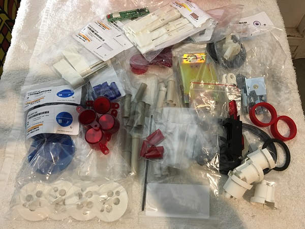
After an initial inspection of the machine and a read of the manual, various parts orders were placed (locally and abroad) for things I knew I was going to need to replace or upgrade. I love getting parts orders in the mail! No doubt a few extra things will crop up as I work away on the machine, they always do. But this lot should just about cover everything.
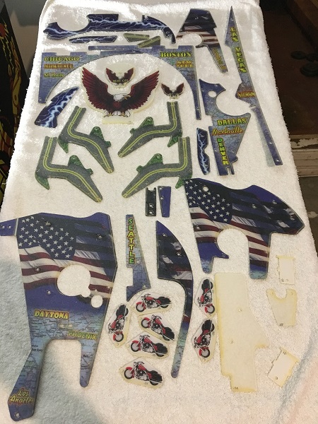
Due to the condition of many plastics on the game, a new full set were purchased. These are from the 3rd edition (Stern) and have different artwork to the originals by SEGA. The plastics are the same shape though and designed for this game. There is another Harley Davidson game, release by Bally, which also has a reproduced plastic set available. But the playfield on that game is completely different and the plastics not suitable for this one. So if you’re wanting new plastics for your Harley machine, make sure they are for the correct manufacturer. The game is going look great with this installed!
One of the first things I wanted to do was remove the AA batteries from the CPU board. I make up my own remote battery kits with parts from Jaycar. They are cheap and easy to make. I like to use the enclosed casing so if they did leak, it’s contained.
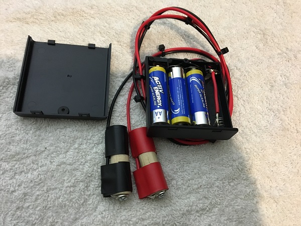
They install directly into the AA battery holder, which means no handling / changes to the board.
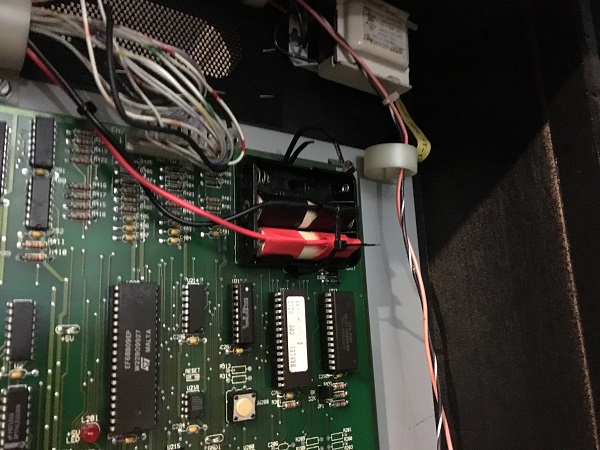
In the headbox, the game uses a fluro tube to light the translite. Both the tube and starter were missing from the game.
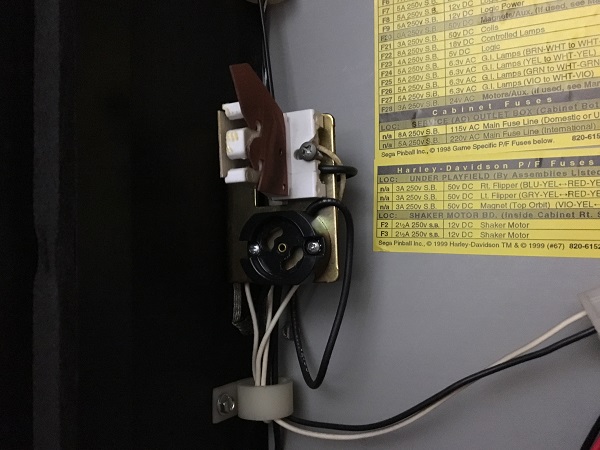
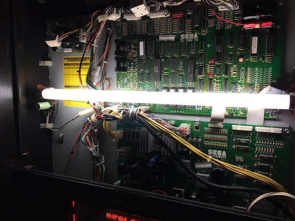
This is easily sorted though with a quick trip to Bunnings to pick up a new tube and starter. Once installed, the game was switched on and the headbox was now lit up nice and bright.
Time to run the game through the diagnostics screens to find some issues look at. First up was testing the switch matrix. There were 6 switches found to not be working. The lamp matrix was all good except for 1 lamp on the pop bumpers.
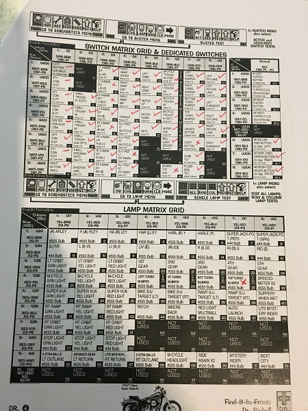
The coil tests were good except for 1 drop target bank (which does work, but the assembly is not together properly – i’ll cover this below) and 1 group of flashers (F3). A pretty good start.
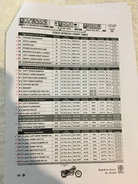
The first failed switch to look at is the missing stand up target at the ramp entrance.
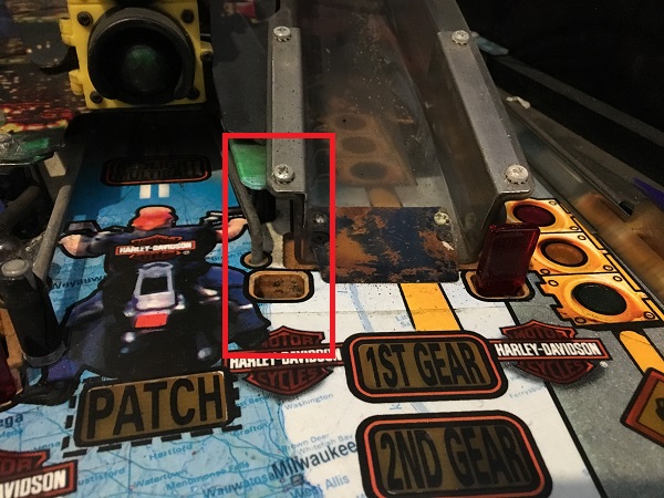
Below the playfield, there are the remnants of the target assembly still attached. The wiring is still there too, so I should only need to pop in a new target to get it working again.
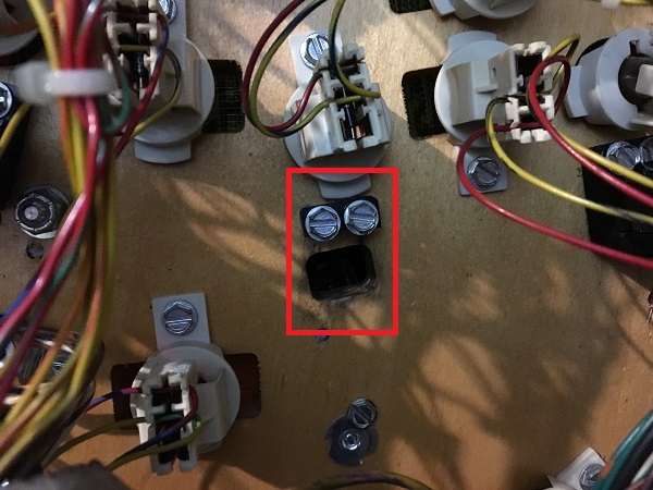
A new target assembly was purchased and installed. The small IDC plug was still under the playfield, so I connected this back up and tested the switch. It was now working, so I could tick it off on the matrix print out.
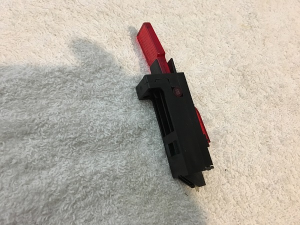
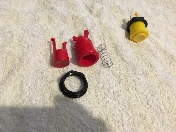
Next switch to look at was the start button. This was an interesting one as it does work if you hold the button in very firm. I disconnected the switch from the button and manually activated the switch with my finger. This worked 100% of the time, so I was happy the switch was functioning correctly and didn’t need to be replaced. I installed it again, but found the issue was still there and it would only register if you held the button in firmly. I had a spare yellow button with the same profile as the red, so swapped it in. Testing with the yellow button now had it registering accurately without having the firmly hold the button in. I disassembled the red button and gave it a thorough clean. It was then reassembled and installing to the game. Now the start button was registering correctly and could be ticked off.
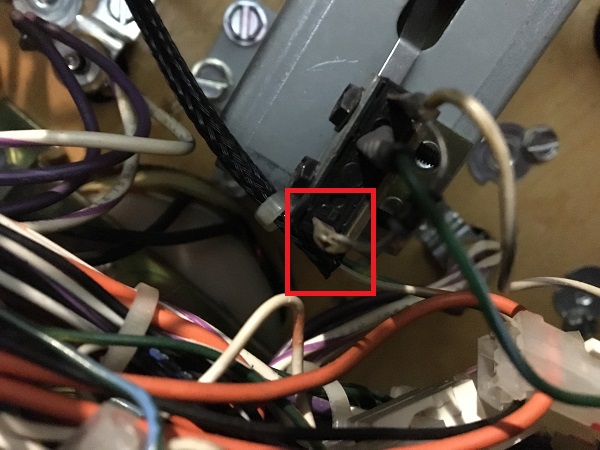
Another failing switch was one located near the VUK under the playfield. This was due to cracked solder joints on the diode, which could freely move around the switch tab. Fresh solder was applied and the switch now registered correctly. Another one ticked off.
The last 3 switches to look at were on the drop target banks. The drop targets have seen better days. On the left side, three of the targets have been smashed and the metal rail behind them bent backwards. It looks like people continued to fire the ball into the area long after the old rubber broke.
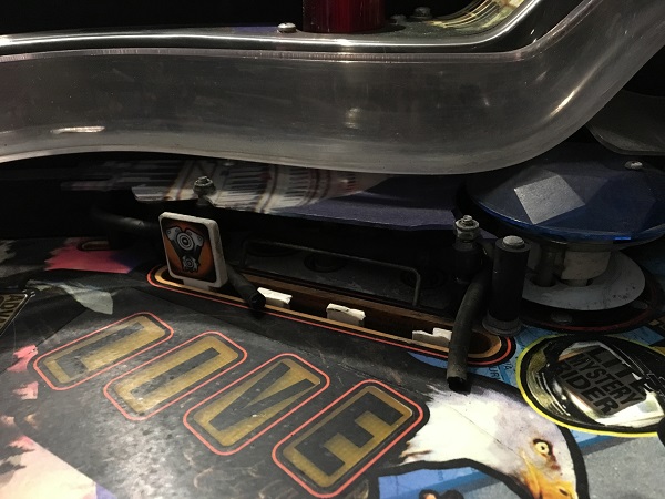
The right side has a different issue though, the reset bar was detached as one of the metal rods had fallen out due to wear.
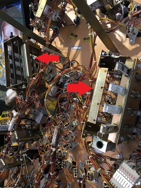
All three switch issues on the drop targets were due to diodes broken on their switches.
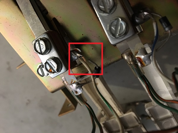
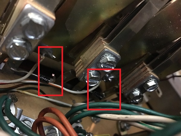
The diodes were soldered back on and the switches tested. All passed and I could tick off the last switches on the switch matrix. A hack on the left drop target bank was there to keep the small bar in place (the same one that had come off the right side). Let’s fix that properly.
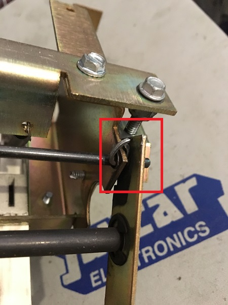
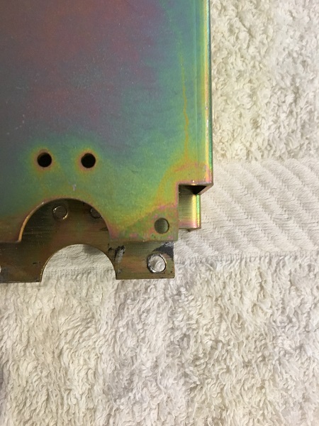
To give you an idea of the wear on the assembly side panels, here is a new piece compared with the original. The small metal rod that sits in here is attached with an e-clip and had worked it’s way out over time. My initial plan was to replace the side panels. But because the sides are reversible, I was able to swap them around so the worn hole would no longer be in use and save the owner $40 in new parts.
Both drop target banks were disassembled and all parts cleaned. New drop targets and decals were purchased to replace the broken and worn out ones. New coil sleeves were purchased along with the missing metal rod.
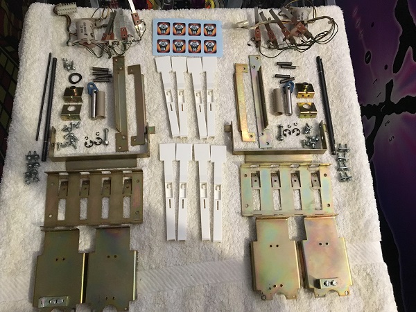
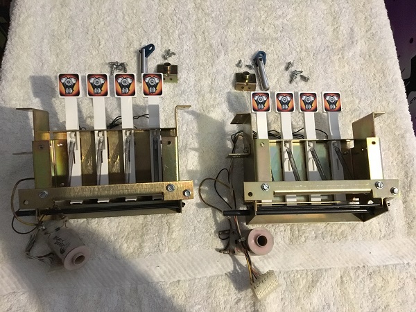
The two drop target banks were rebuilt, ready to go back into the game.
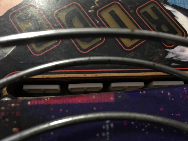
With the target banks installed again, I noticed that the targets were sitting a little lower than I’d like.
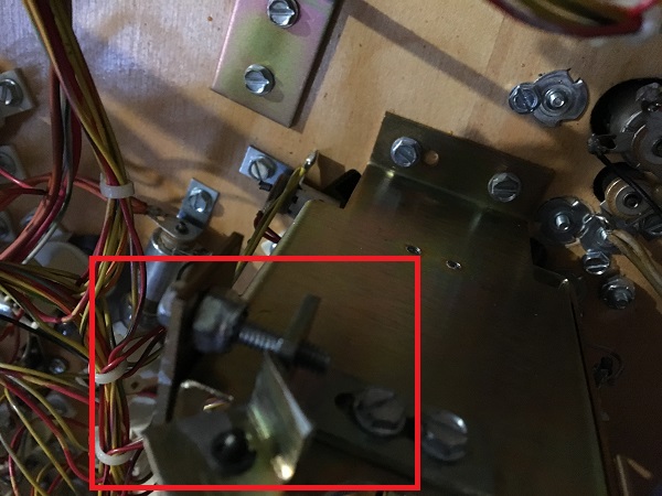
You can adjust the height at which the targets set when dropped with a small arm on the side of the target bank. This limits how low the reset bar can drop, which then dictated how low the drop targets can fall once hit.
After a few adjustments, I had the targets sitting just below the playfield surface.
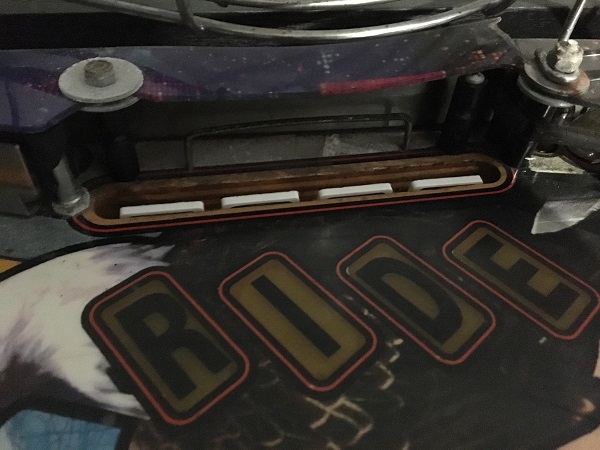
Now that the switches were all ticked off and drop targets rebuilt, I wanted to sort out the single lamp that wasn’t working. This was due to a loose diode and just required solder to fix it up.
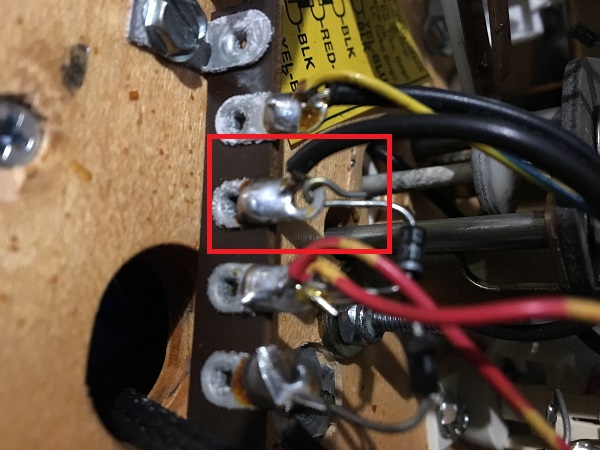
A small task I had made a note of when the machine arrived was to sort out the cabinet wear around the flippers. Both sides of the cabinet suffer from it.
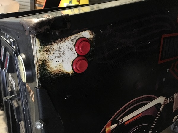
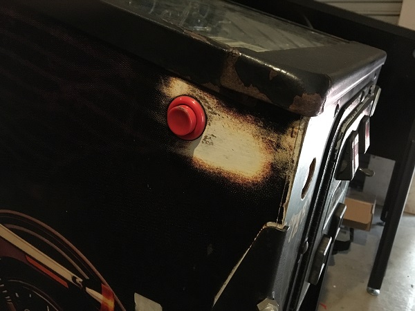
I sourced a set of metal cabinet protectors and also new buttons.
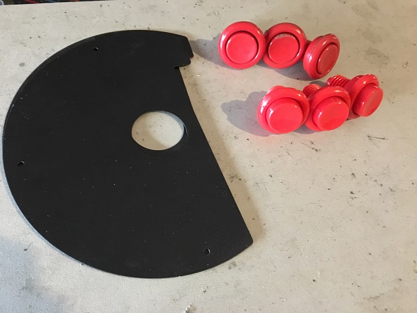
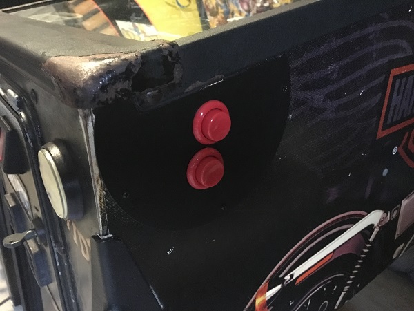
One issue with the cabinet protectors though is they are designed for one button, and Harley has two buttons on the right side of the cabinet. While chatting with the owner about them, we decided the best approach would be to mark out the hole position, screw the panel into a spare piece of wood, and then drill out the button hole with a metal hole saw. This worked out perfectly and allowed me to get the second button hole cut easily.
To round out the first update on Harley, I wanted to work through the apron and the few assemblies that it consists of.
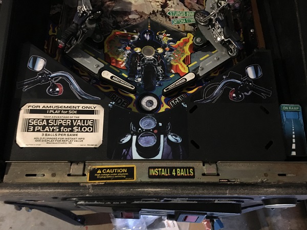
First step was to remove the apron so I could see how things looked underneath. I made a small swipe with my finger near the ball trough to show the level of dust that had collected. It wasn’t too bad considering it had been sitting still for many years.
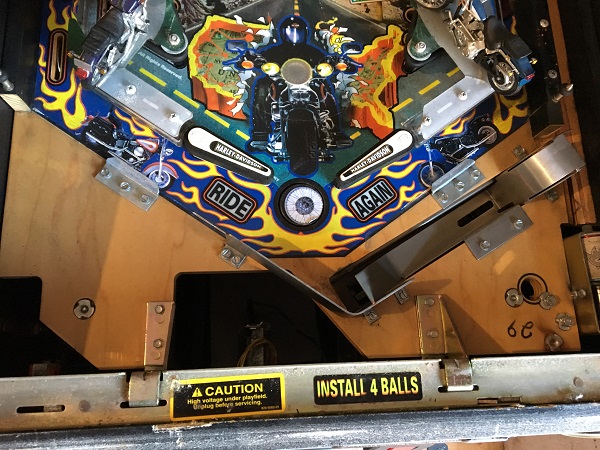
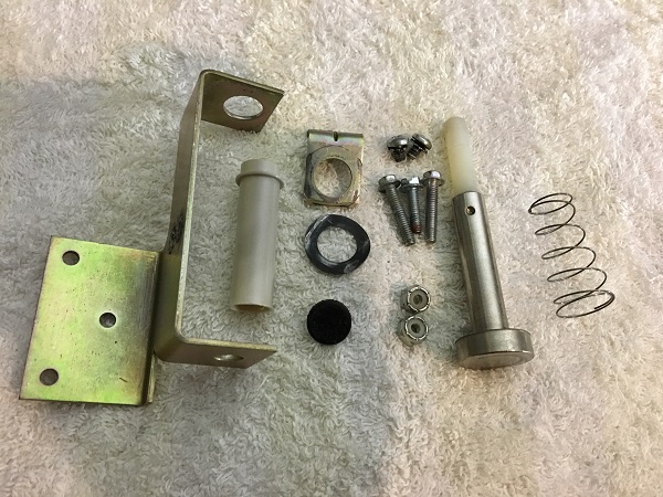
I removed all the metal parts and assembles from the apron area for cleaning. First up was the ball trough. A new coil sleeve and rubber grommet were purchased to replace the old ones. The return spring was missing off the assembly, so a new one was purchased. Without it, the plunger would not return to it’s normal resting position. All parts were cleaned up before the trough was reassembled.
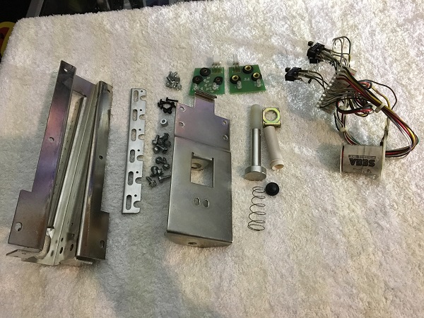
Next up was the auto launcher assembly. This was complete and with no missing parts. A new rubber grommet and coil sleeve were purchased to replace the old ones. The assembly was disassembled and the parts cleaned.
With the assemblies done, the small metal pieces from the apron went through the tumbler and then cleaned by hand.
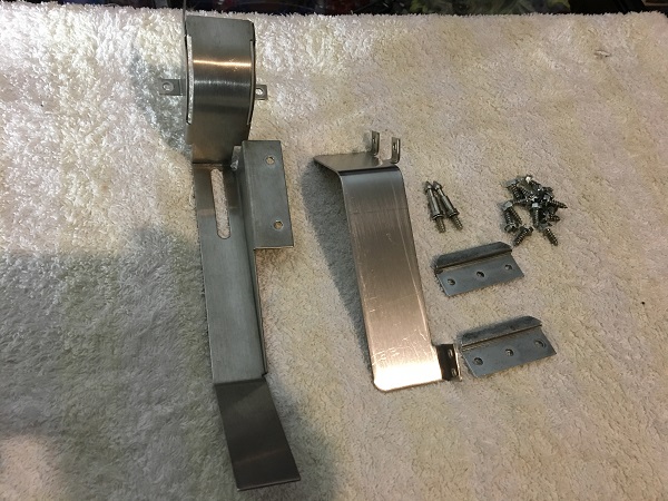
Since the parts were ready to go back into the game, now it was time to clean the playfield. I used Nifti, which removed most of the filth and a small bit of Novus 2 on the more stubborn bits. It was finished off with Novus 1. The two metal arms that hook the playfield into the lockdown bar receiver were also cleaned up.
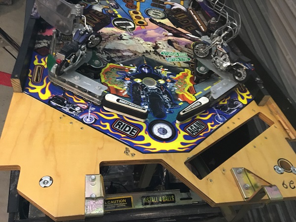
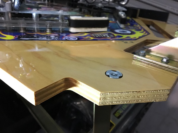
The metal parts were installed back onto the playfield, along with the ball trough and auto launch assemblies.
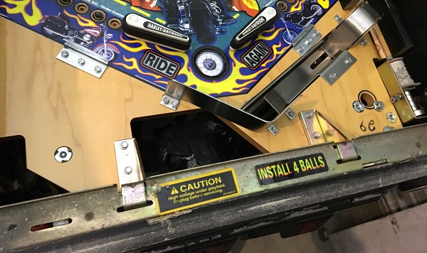
Lastly was the apron. The metal frame is still in excellent condition and was simply given a wipe down to remove any surface dust and filth. New cards were printed up and installed. Sadly pinballcards.com didn’t have a classy Harley Davidson set done, so I had to go with a simpler design. While not as fancy as the ones PinballCards make, they are better than the pricing ones. Loose spots on the apron decals were stuck back down again. It was then installed back onto the playfield.
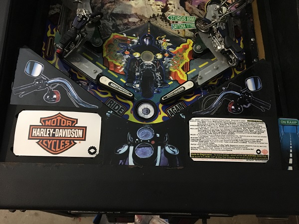
That’s it for the first update on this Harley service. I ended up getting sidetracked and not resolving the random resets and non working flashers. I have spent time eliminating some things though. Often the random resets are the result of 5V issues, but that doesn’t appear to be the case here from what I’ve diagnosed so far. The flashers are most likely due a bad transistor on the driver board. Hopefully I’ll cover those in the next update. I will also be looking at the up post, flippers and sling shot assemblies. There are some more presentation things I want to do on the cabinet, but will most likely put those off until the final stages. Lots more to come though, so stay tuned!
