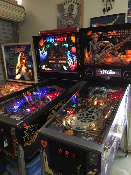
Welcome to a new Repair & Service log series. I’m still working away on machines for other people, but it feels good to also be making time to work on a game of my own again. This time I’ll be going through a Bride of Pinbot, which has the 2.0 upgrade kit from Dutch Pinball installed. Originally released by Williams in early 1991 and over 8000 machines made, it’s a game I’ve been wanting to own for awhile. The kit from Dutch Pinball was released in late 2014 and updates the machine to a colour display with an entirely new rule set. It also allows you to switch to the original game rule set too – which basically means it’s two games in one. It runs the original game under emulation though and as a result there is some sound quality issues on a couple of the original speech sounds. I’m told this is due to the quality of the original speech clips being played out of the updated sound system. All up though both games are a hell of a lot of fun to play. I plan to do my usual clean and rebuild of the game, with additional plans in the future for a playfield swap (game came with a clear coated playfield) and new cabinet decals (to be purchased later). For now I’m keen to tackle it in small doses to keep the game in a playable state as much as possible.
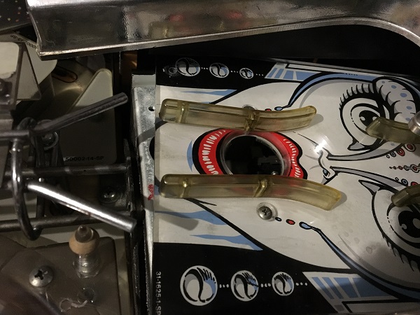
The first issue to sort out was one of the brides face plates not screwed in. The previous owner had mentioned to me the mouth coil was not popping the ball out 100% of the time and would look at it before the machine was shipped down to me. He must not have screwed the face plate back on as it arrived like this.
Thankfully I’m overflowing with spare parts and so finding a suitable screw to attach the plate was easy enough to fix it. The next issue was not so straight forward.
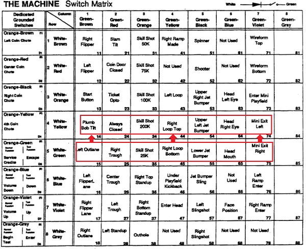
After a couple of games, I noticed some issues with a few of the switches. Most notably was the left outlane, which would trigger a tilt warning. Putting the game into the original BoP ruleset, switch issues became more obvious as the face is used more and I was seeing strange behavior around the eye and mouth switches. Putting the game into test mode, a pattern was seen. All 7 switches on row 5 would activate the switch above it in row 4 (and only the row 4 switch – none of the row 5 switches appeared on the display during testing).
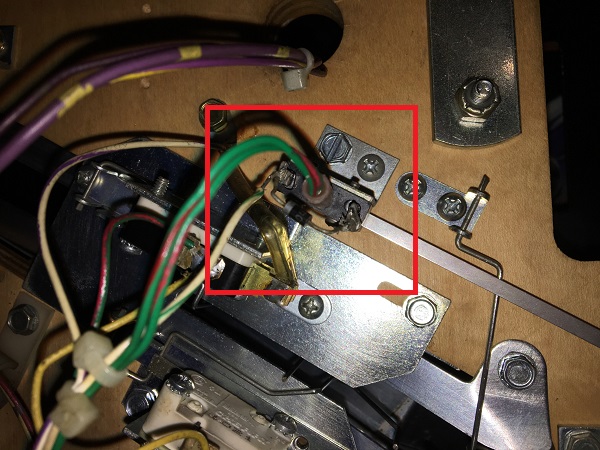
Interestingly, activating row 4 switches did not activate row 5, so they were not shorting. With the game in switch levels test mode, only 1 switch would activate per switch. I inspected each of the switches on row 5 and found an issue with the right trough switch. Looking at the right trough switch, I noticed that some soldering had been done to it at some point in recent weeks/months/year (not sure how exactly how recent) – and the switch wire (white+green) is connected to the banded side of the diode. I believe this should be connected to the non banded side as per the other switches across the machine. The switch itself looked like a replacement as the activating arm was far longer than the shorter one seen on older machines.
Thinking that this switch was causing some sort of short, I disconnected the wire from the trough switch and then tried the other switches on row 5, but then none of them would register. They only register (all be it incorrectly) when the trough switch is engaged (as a side note, the trough switch (25) would be activating switch 24 – which is marked in the manual as “Always closed” which would explain why there is no ‘missing ball’ error preventing a game from starting).
I moved the wire to the correct switch lug on the right trough switch. This resulted in no switches on row 5 working. I ran through all switches on the machine again and marked them off on the switch matrix to confirm that only the row 5 switches were failing and there were no cases where multiple switches were being reported.
On the P-ROC board, there are a series of LM339 chips which are in charge of the direct and matrix switches on the game. Looking at the P-ROC schematics I found which chip was responsible for row 5. I replaced this chip and booted the game back up.
At this point, the switches in row 5 started to register correctly. That is, until I activated the right trough switch again. At this point, the switches on row 5 became intermittent until they stopped registering entirely and was again left with row 5 not working (but all other switches fine).
I replaced the LM339 chip again and this time also replaced the right trough switch. Booting the game back up and testing the switches again, row 5 now registered correctly and the right trough switch worked correctly. I tested the switches on row 5 on repeat for a few minutes, with a heavy focus on the right trough switch and no more failures or intermittent behaviour was seen.
So from what I can tell, the right trough switch was the cause – not just the incorrectly wired lug, but the switch itself. I don’t quite understand why the switch was causing the LM339 chip grief, but it’s removal from the machine was necessary. Thinking maybe the diode was shorted or open, it was removed and tested, but it tested fine. Since fixing, I’ve played a number of games on both BoP and Bop 2.0 modes and both have run without any of the switch issues that were there.
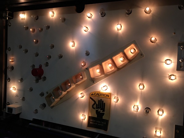
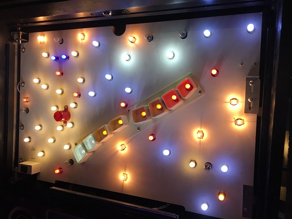
Now to look at the next on arrival issue with the game. A number of bulbs on the headbox GI were not working. They are located mostly on the left side of the headbox, although a couple do extend out to the upper and lower corners on the right side.
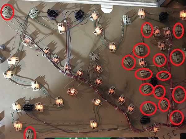
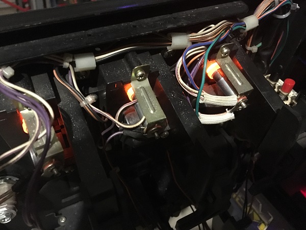
At first I thought it was probably just a number of bad bulbs. Some owners aren’t fussed about it so never bother to replace them. I found that after replacing a few of the non working bulbs with brand new ones, they still didn’t work. Swinging the headbox door open, I had a look at the reverse side of the sockets. I soon saw a pattern indicating something more sinister was up. All but three of the non working globes were running off the same circuit, connected by a brown wire. None of the bulbs on the brown wire were working.
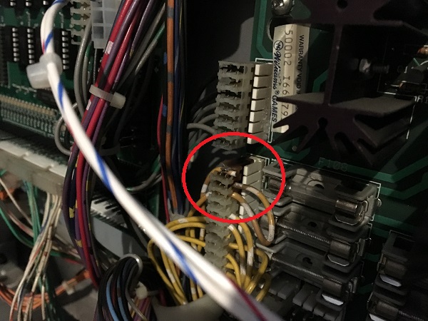
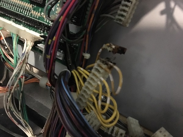
The couple of non working bulbs running off the green wire were replaced and this got them lighting up again. Since none running off the brown wire were working, there was an issue up stream to look at. My first thought was a fuse. I had a look at the fuse chart inside the headbox to see which fuses were allocated to the headbox GI so I could inspect. But when looking at the fuse block on the PCB, I could see the burnt GI connector (located just below the fuse block) was where the issue lay. Where the brown wire should join the connector, it had burnt away. Someone had attempted to repair it in the past and just simply soldered the wire to the header pin – not very well though as the wire had come loose and was hanging down at the base of the headbox.
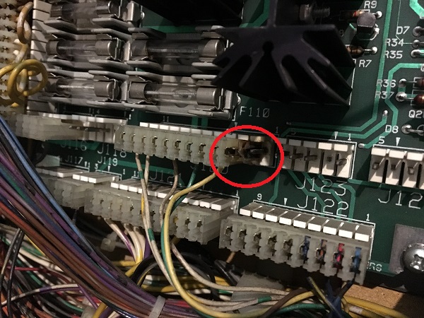
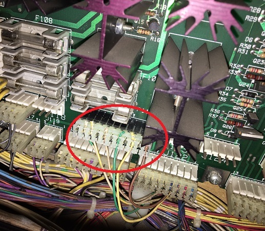
Another connector in the area (sitting just to the left of the fuse block) also caught my eye, and it too is part of the GI circuit. This one too had bad signs of burning across at least two of the connector pins.
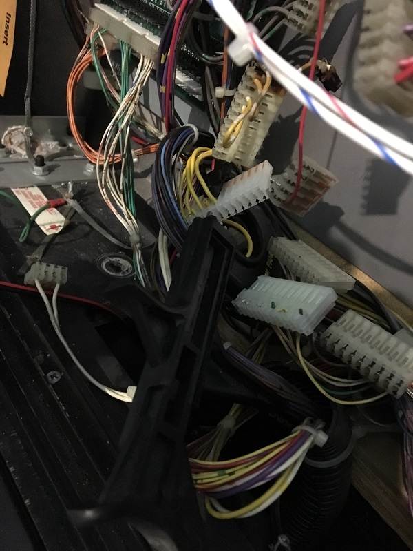
Let’s fix these properly. To do this, i’ll need to get the board out of the machine. First, photos were taken of all the connectors around the board to ensure everything went back on correctly. It’s important here as a couple of them are the same size, keyed the same and also sit next to/above each other so can easily be put back in the opposite spots. When removing the board, one of the burnt connectors began to crumble.
With the board removed, the plastic on the old connector was cut into several smaller pieces and then pulled off the board. Then the solder on each pin was heated up and the pin gently removed from the PCB. Excess solder was cleared away and I installed the new pin headers on both connectors that had been burnt. I find this approach the easiest method for replacing header pins. Once done, the burnt connectors in the headbox needed to be replaced also. I have a tool that makes replacing the IDC plugs easy and each wire was transferred from the old connector to the new one.
You should always replace both the header pins on the board and the connector. Both connectors and header pins are now in a much better state and as I switch across to LED’s, there will be less draw through the connectors which should prevent it from happening again.
Now that the connector and header pins had been replaced, I also swapped out a lot of the old bulbs from the headbox GI with spare LED’s I had. I plan to play around with the colour combination and type of LED’s at a future date. For now though I mainly wanted to ease how much power was being drawn by the headbox GI, so this layout will do for the time being. The replacement header pins and connectors did the trick though to sort the issue out and the LEDs sitting on the brown GI circuit were now working.
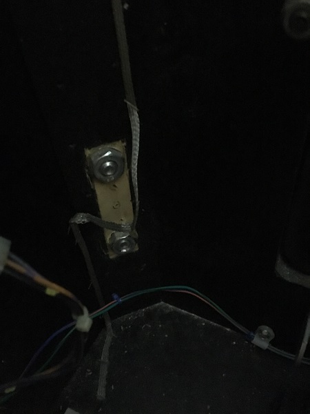
On arrival, there was trouble getting the front right leg installed as the bolts wouldn’t screw in. It was found that that leg plate that sits inside the cabinet was missing. The previous owner had not mentioned this and had left the nuts inside the cabinet for transport. The machine was transported on it’s back, but luckily one nut was found floating around in the base of the cabinet just inside the coin door. This allowed for the leg to be attached with 1 bolt. With the game set up, the playfield was lifted and the second nut found at the very rear of the machine and the second leg bolt installed.
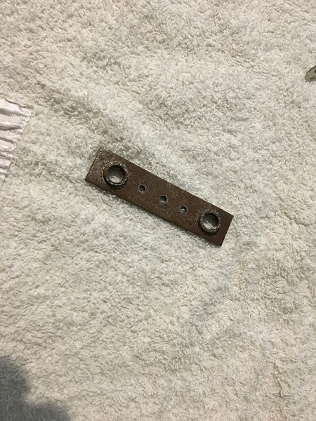
I have several containers of spare parts and was pretty sure I had picked up one as part of my junk parts purchases awhile back. I dug through the containers and found a secondhand leg plate, which I could install to do the job properly.
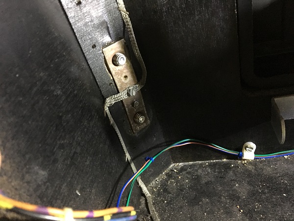
The plate was screwed into position on the corner of the cabinet, with the earth braid attached. The leg bolts were then installed again. This is the reason I only throw out spare parts when they are faulty / failing as the most random parts come in handy at times.
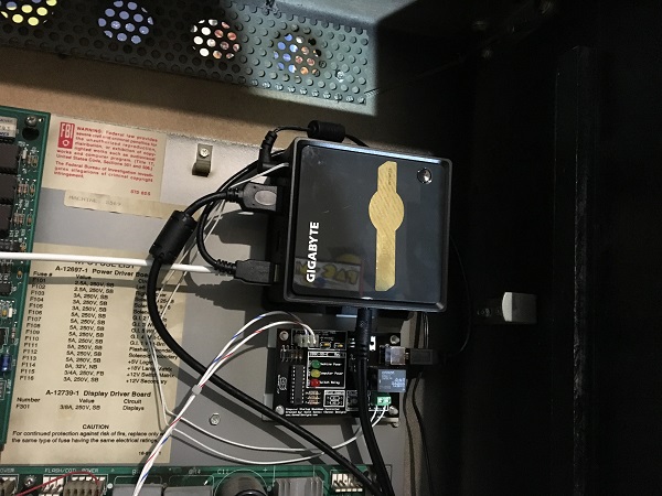
The next issue to sort out was the “Live” account. This one didn’t really bother me much, but it was something I was keen to get working as it’s a neat feature of 2.0. One of the core components on the 2.0 kit is a small NUC style computer which is installed into the headbox. It runs Windows 7 and has networking capabilities (both physical and WiFi). A keyboard and mouse can be connected up to access it.
The network features allow you to connect your game online, which communicates with the Dutch Pinball “Live” page where your machine profiles are synced and it can stream the DMD display, allowing people to watch your display online during play. You can set up a profile for each individual player which will track their initials, own top 25 scores, stats and also trophies (achievement like things from Playstation and XBox console games – I love this feature!).
I hooked up a mouse and keyboard, then connected my BoP 2.0 up to my WiFi network. To test, I brought up Internet Explorer (shudder – I hate IE, but to test that the WiFi was connected, it was necessary). So there I was, browsing google via my BoP 2.0 display, connected to my network. I couldn’t help but laugh at the absurdity of surfing the web from my pinball machine. I then went to the Live page account that was provided with the machine, but it could not detect my game being online. There is a setting in the service menu which needs to be enabled for it to communicate, so I confirmed that was enabled. After double checking the network settings and also the service menu settings on the machine, I did some googling for similar issues. Not having any luck, I decided to contact the DP support email to see if they could help. Just over 24 hours later, I had an email reply with the corrected account details and my BoP 2.0 was now online with the profiles synced and DMD streaming enabled. Now my profiles sync and when ever my game is switched on, the DMD is streamed for people to watch.

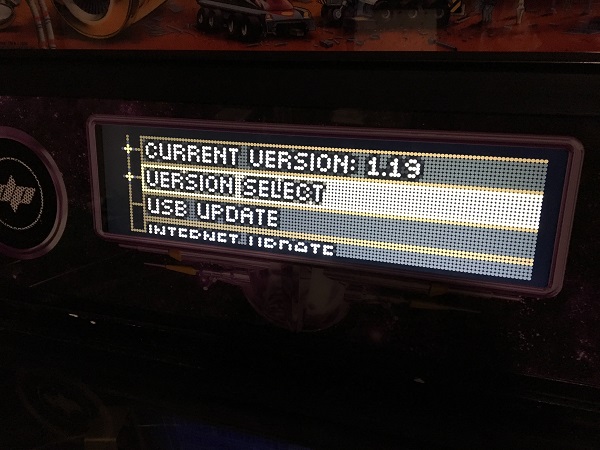
After playing a few games, I decided to update the game software. The machine was currently running 1.16, but could be updated to 1.19. Looking at the version change log, I saw a number of features and fixes that had been added to the game, so decided to do it. The software was downloaded to a USB stick and then inserted to the NUC in the headbox. From the service menu, you can install the software or revert to a previous version. This is handy as it allows you to easily revert if you find the current version is causing problems. The software was updated to bring the game up to the latest version.
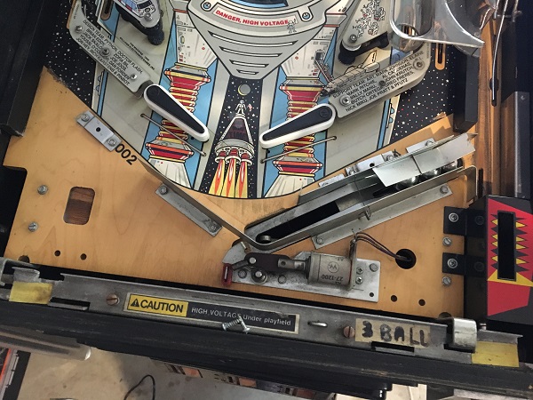
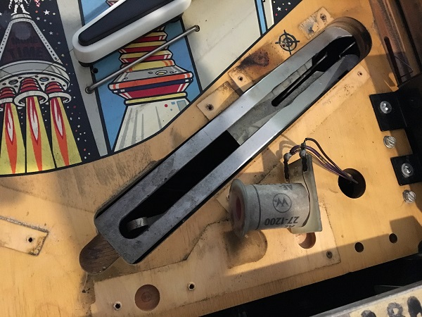
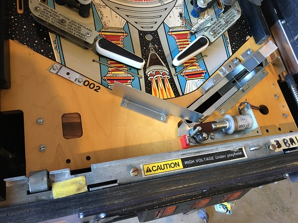
Another issue that was present on arrival was the ball serve. It would often take 3 or more attempts to kick the ball out into the shooter lane. A quick visual inspection of the assembly showed it to be quite filthy, so I suspect a service will sort this out. It could simply need a clean or there could be a worn part in need of replacement. I’ll find out when I get the parts out. Rather than just rebuild the single assembly though, I may as well remove the apron and service the whole area. It’s always my starting point for a rebuild, so let’s dive in.
The apron was removed to find the area in a reasonable state. A thin layer of dust sits along the surface and the trough needs a clean. But no nasty surprises and will clean up fine.
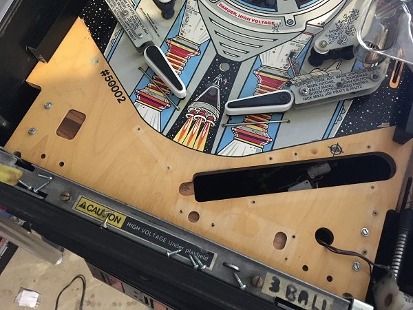
The ball guides and out hole assembly were removed for cleaning. There was the usual collection of crap in the ball trough, but this will clean out fine.
The last of the ball trough pieces were removed. The playfield area was cleaned and then polished with Novus.
The metal parts from the apron area were cleaned up. Any small pieces went through the tumbler, while the larger pieces were cleaned by hand. The switch arms from the trough plate were removed for cleaning too.
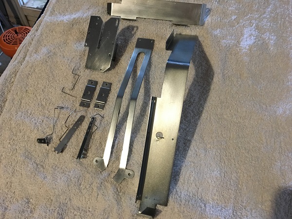
There are two assemblies that make up the apron. The first is the outhole kicker, which sends a drained ball into the trough. The second is the ball serve, which kicks a ball out into the shooter lane. Both assemblies were dismantled and cleaned. New coil sleeves were sourced and the shooter lane guard was also removed and cleaned too.
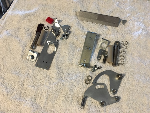
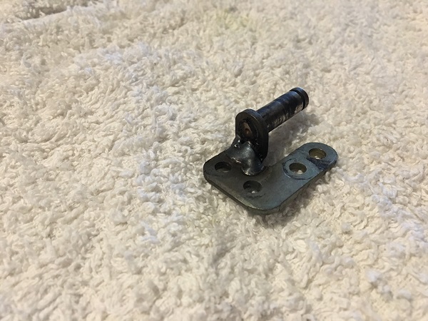
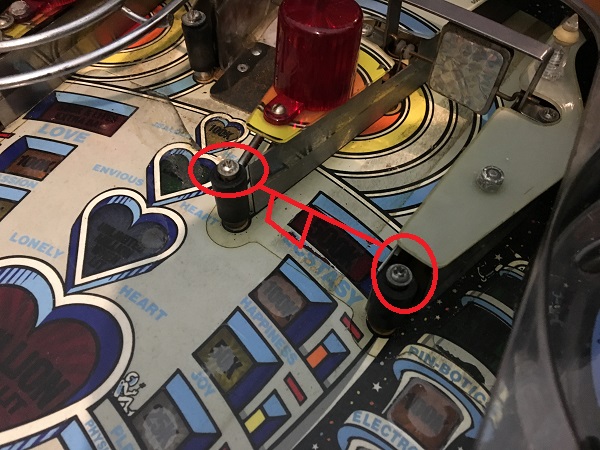
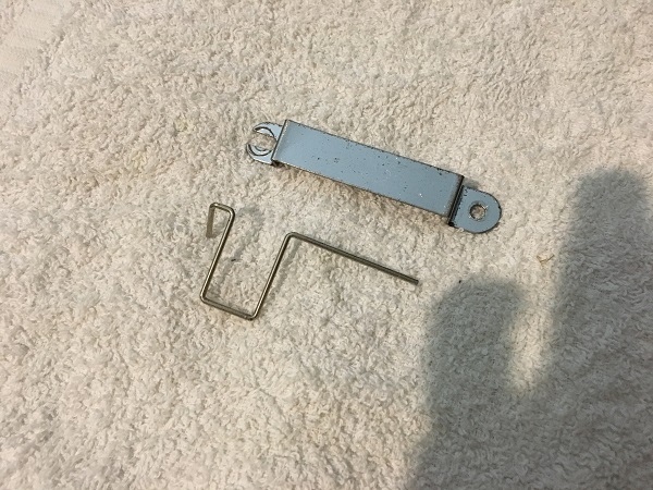
The mounting bracket for the eject arm had been worked on before, with visible weld signs. The pin was also quite loose, so this will be replaced. It could well be the cause of the constant failed ball serve attempts.
The assemblies were the put back together and installed back on to the playfield. The metal rails and apron clips were then installed too, leaving the area looking visibly better than before. The kicker and ball serve assemblies also had much nicer movement after cleaning.
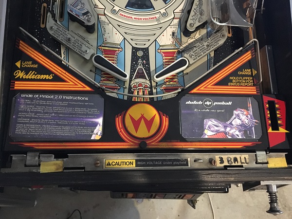
To complete the work on the apron, new instruction cards were printed up onto glossy photo paper and then laminated. Both the apron and shooter housing were cleaned, along with the metal bar that attaches to the apron. The ball serve assembly was tested across a few games and it was much better now, no longer needing multiple attempts to kick a ball out into the shooter lane. Another issue that can be marked off as fixed.
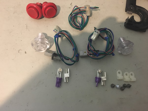
Now that I had the apron area cleaned up and the ball serve assembly serviced, I wanted to add a little something to my machine. One of the first upgrades/mods I wanted to make to my BoP was back lit flipper buttons. I’ve done this on some of my other games (X-Files, LAH and Pinbot) and it’s pretty easy to do. You can buy premade kits, but I do the kits up myself as they are quite easy and cheap to make. I connect them together with IDC plugs so they can easily be removed from the machine and also if I need to remove the coin door (which I will when freshening it up in a later update), I can just disconnect the mod in seconds. All up it costs about $12 in parts. The tired old red buttons were removed, ready for the kit to be installed.
The power for the button LED’s comes from one of the sockets on the coin door. I have swapped the three globes on the coin door pricing plates to orange LED’s too. I plan to spend more time cleaning up the coin door at a later date. The wires run along with the coin door wiring to just inside the coin door, connected to via IDC to a Z header pin for easy disconnect.
Inside the cabinet, the sockets and LED’s are installed beside the flipper buttons. I find using the bendy style LED’s offers a bit more flexibility in terms of angling and position around the flipper switches.
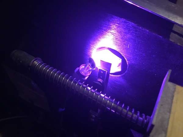
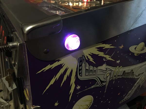
Outside, the buttons glow nicely and give off a really cool effect. I plan to add more purple across the game in terms of lighting, so purple lit flipper buttons should fit in nicely.
While I was in the zone of creating LED sockets, I decided to add two new ones under the apron. One to shine a LED from the outhole and the other to shine into the shooter lane. For now, I’ve used 4+1 LED’s in cool white, but may switch to another colour (or a combination) once I start settling on what colours I want to use where on the playfield. The LEDs draw their power from the right return lane globe under the playfield.
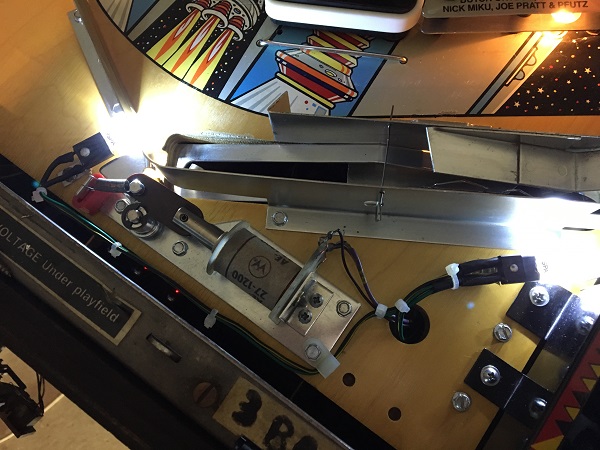
It adds some extra lighting around the outhole and shooter lane. I’ll get a better idea of how it looks once I start switching the lower playfield area across to LED’s. I’m not a fan of mixing LED’s and bulbs – I prefer it to be all of one style. For now though, I can live with the mix as I continue to work through the machine.
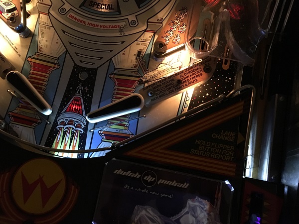
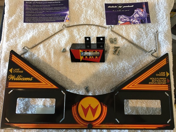
The shot which leads up to the pop bumpers should have a one way gate across the entrance. The gate takes up about a third of the opening, which helps prevent certain drains when the ball comes down on the left side of that path. This gate was missing on my machine.
Turns out that buying the gate isn’t so easy. After looking at several parts suppliers locally and overseas, I came up empty handed. However I was able to purchase the wire for the gate locally. After a quick dig through my parts box, I came up with a secondhand gate frame, which would fit perfectly. The frame needs a bit of a clean, but for now I’ll put it on the game so I kill off those nasty ball drains. When I’m going through cleaning this area of the playfield, I’ll run it through the tumbler.
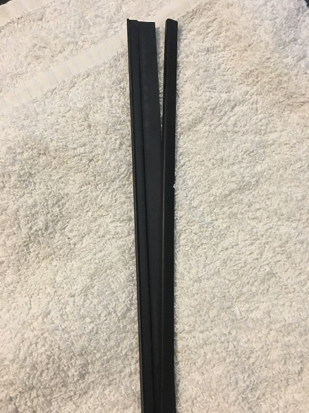
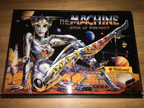
Next on my hit list is the translite trim. The right side is badly broken and flaps around. The top piece is not as bad, but split in a similar fashion. These will be replaced.
The reverse side of the translite is in pretty good condition. The gaps are an intentional part of its design. There are some dirty marks across it though and these will be cleaned up.
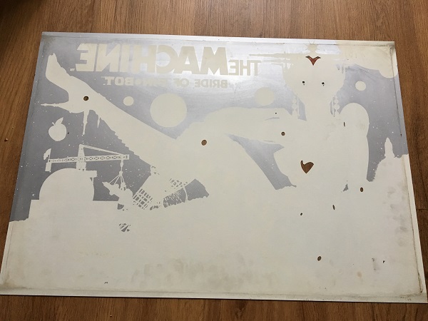
The glass was also cleaned up both sides and then the translite installed again with the new trim set, ready to go back into the machine.
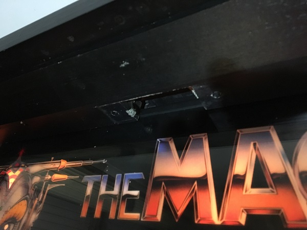
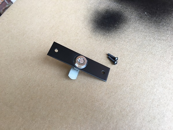
Now that the translite was cleaned and the trim replaced, I wanted to address one small item to close out this update. The lock for the translite had been removed at some point in the past and left out of the machine. The lock, plate and key arrived with the machine, but in a bag. I wanted to install this once again. The screws were missing however, so a new set were ordered.
I cleaned the lock plate and then sprayed with satin black to freshen it up.
The lock and translite were then installed back into the machine. That’s it for the first update on the repair & service of my BoP 2.0. I was disappointed about some of the issues the game arrived with, like the burnt GI connectors and especially the switch matrix issue that the seller never mentioned even when directly asked about any existing switch/coil issues before purchase. Next up I’ll be doing more work in the lower playfield area by rebuilding the flippers and servicing the sling shots. I will swap the insert bulbs across to LED’s too. Still a lot of work to be done to get the machine to a level I’m happy with. Bigger tasks for next year will be the playfield swap and cabinet redecal, but all in good time.