A good way to continue working on pinball machines (without going broke buying them), is to work on other peoples machines and bestow to them the same love I give mine (the machines that is, not the owners..). I’m always on the look out for a new Pinball project to work on as I love giving them a new lease on life, but pickings have been slim lately. The universe has other ideas though and through a chance message, I was asked if I could work on some machines that needed a bit of TLC, with Whirlwind being first on the list. How could I refuse? 🙂 This isn’t a restore but also not a simple service either. I’ll be doing my usual rebuilding and cleaning of all assemblies, along with fixing any game play issues and giving the machine a bit of a face lift along the way. I don’t have plans to do any board work and the owner has a few requests on specific things he wants addressed, which i’ll be following. Whirlwind is a great game and I’m very excited to be working on it. Once complete, it’s going to be hard to let the owner take it home.
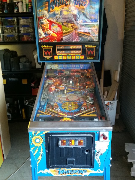
First I’ll start with a quick overview. The machine is a container pin from a few years ago now. All things considered, it’s not in bad shape and is in good hands with it’s owner. After a solid clean up, it’s going to run so nicely for many years to come. The first thing that stands out with the machine is a lot of the GI on the playfield is out. There are a few globes running on the top half of the playfield, but everything in the bottom half is off. Back box GI looks to be good though and I like the use of #455 flash bulbs behind the storm cloud on the translite. The display is perfect and translite in good condition.
The biggest visual problem I could level at the machine (looking past the filth build up) are the broken plastics. It’s obvious the game has taken quite a beating in its past. I won’t be replacing any of the plastics during this service, although I will clean what’s there and also flatten out some of the warping. I will keep an eye out for any replacement plastics though, so the owner has the option to buy them if desired. If anyone has some pieces that might suit, let me know and I can pass the details on to the owner.
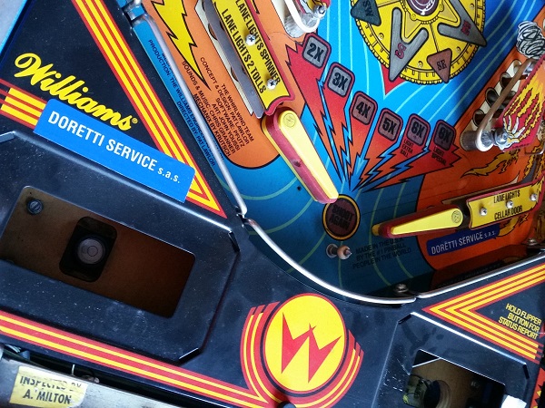
The old company that used to route the machine has “kindly” placed their sticker on the apron and also on the lower right drain on the playfield. The owner has requested they come off, so i’ll be removing them when the time comes. I am a bit concerned the one on the apron may lift some of the Williams apron art off, so will need to be careful when doing it. There are no pricing / instruction plates on the apron, but I should be able to print off some nice ones to lift the machines presentation.
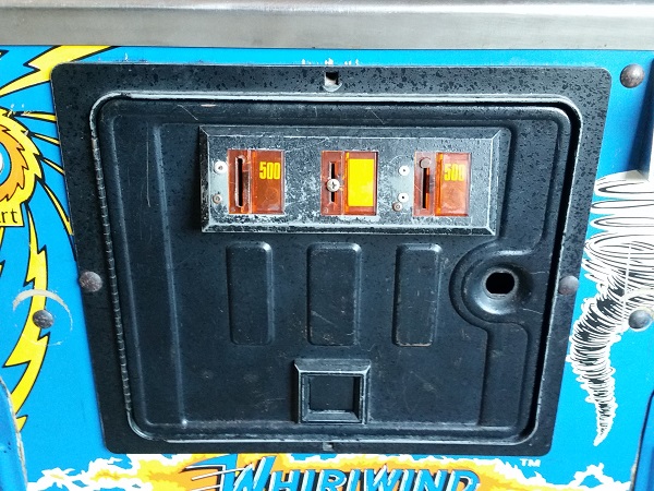
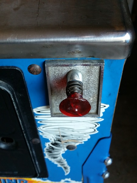
The front of the cabinet isn’t too bad. There are 2 bolts missing from the coin door and also some pop rivets in the coin entry housing. The owner has asked me to clean this up and give it a face lift. I’ll see what I can do about some nice pricing plates too. The shooter rod has seen better days and will benefit from a good service. The side cabinet art isn’t too bad either given the machines age. There are some marks which I should be able to clean up.
After having a look over the machine and making notes on parts that would be required for the rebuild, I put together a few orders so I could get under way with the repair & service. I have no doubt a few extra things will pop up along the way (they always do) as I work my way through the machine.
One of the first things mentioned to me by the owner was he wanted the batteries removed off the CPU board. This seemed like a good place to start on the machine.
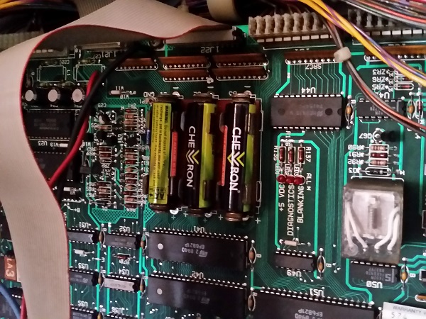
When I worked on my Pinbot (which is also a System 11), I left the CPU board untouched and created a remote battery pack that would plug in to the battery holder. This way the board remains untouched and the batteries are off the board, posing no further risk should they become forgotten and leak. To build the remote battery kit, you need two battery sized pieces of dowel, some eye conntectors, screws, wire and a 3 x AA battery holder. All up it costs a little over $5 to make.
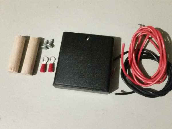
Once built, you can simply plug the kit into the board and rest the battery pack at the base of the headbox. I tested the voltage coming off the battery pack, and a nice 4.8V was read. Out of curiosity, I tested the old batteries and they were only outputting 1.1v. I really like these AA battery cases as they will trap any battery leakage and are cheap to replace if needed.
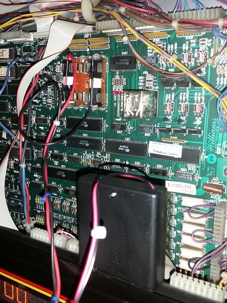
While I had the back box open, I wanted to have a quick look into why the GI on the lower half of the playfield was out. The manual shows 4 fuses on the interconnect board (the one that sits behind the display and speaker panel) that are for the playfield and back box GI.
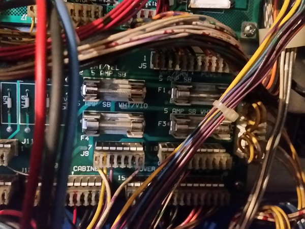
The GI in the back box is running fine, and the top half of the playfield looks to be OK (except for a handful of globes that need to be replaced). The lower half is completely out, as is the coin door. I removed all four fuses and found F2 to be blown, while F1, F3 and F4 were all fine.
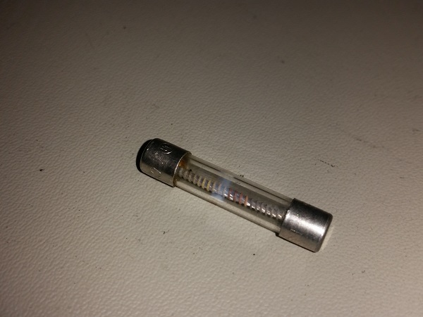
This was replaced with a new 5A slow blow fuse and the machine switched on again – we now had GI running on the lower playfield area and coin door (minus a few dead globes).
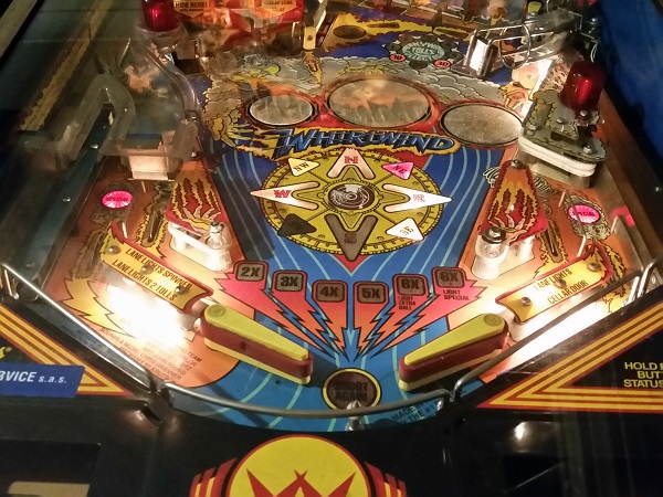
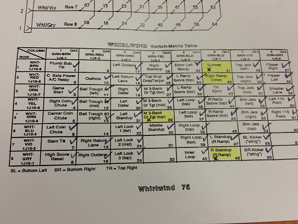
Before I start work on servicing and rebuilding the assemblies, I wanted to take some time to run through the switch, coil and lamp test modes to ensure everything was working. The owner alerted me to an issue with the ramp switch. The ramp assembly is very much like the one on my Pinbot. After observing it’s behavior in game, there is certainly something not right about the switch which tells the game if the ramp is up or down. By the look of it, the game never detects that the ramp is down, so continually triggers the ramps release coil. He felt the switch was faulty and the cause and I’ve marked it down for closer inspection. I’ll get to that switch shortly though. For now, I put the game into test mode and ran through both the coil and switch test modes. There are 56 switches in total, laid out across an 8×8 matrix (8 switches are unused in this game). After running through the test mode, I discovered that there were three other switches that needed to be looked at as they did not register during the switch test:
1/ The top drop target on the 3 bank (#29)
2/ Spinner (#41)
3/ Right stand up (#48)
Since I was waiting on parts to arrive at this point, now seemed like a good time to investigate those non responsive switches and also look closer at that ramp switch. The switch contact on the stand up target was cleaned, but it still did not register. The playfield was lifted up to investigate. I had a look at the spinner switch, which sits right beside the stand up target that was failing. The spinner switch is connected to a microswitch, which I found interesting as I was expecting a leaf switch. What caught my interest though was a ground wire running between these two switches, chaining the ground together, but no wire continuing the chain. This means the ground on both these switches was not connected up to the rest of the machine. This would indeed cause a problem!
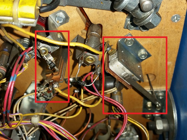
An even closer inspection showed a loose wire tucked away behind all the other wires – this wire should be connected to the stand up target, to join it and the spinner to the ground chain.
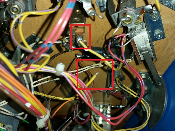
The soldering iron was fired up the the ground wire reconnected. I’ve had this happen a few times on my Pinbot, where the ground wire on various switches has come loose over time. It’s the same yellow wire. The game was switched back on and into switch test mode again. Both the spinner and right stand up targets now correctly registered in switch test mode. So that’s two switches down – two more to go. Next up was the drop target switch. The 3 bank drop targets use optos to detect when a target is hit. There is a small plastic fin on the back of the target, which passes through an opto interruptor (I’ll do some more detailed photos when I service the assembly in a future update).
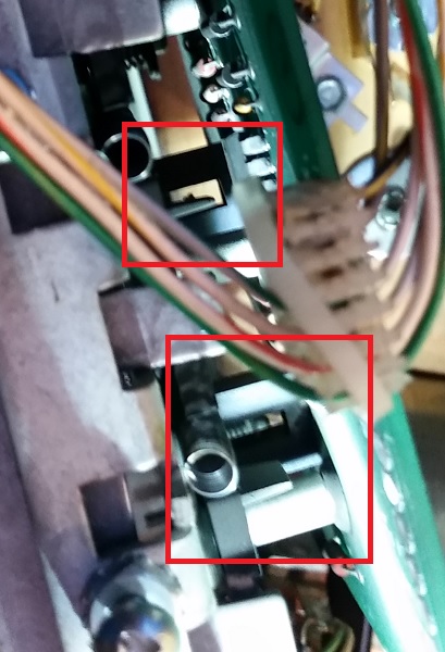
Looking at the PCB attached to the drop target bank, I could see the issue – the opto component was missing from the PCB for the top drop target.
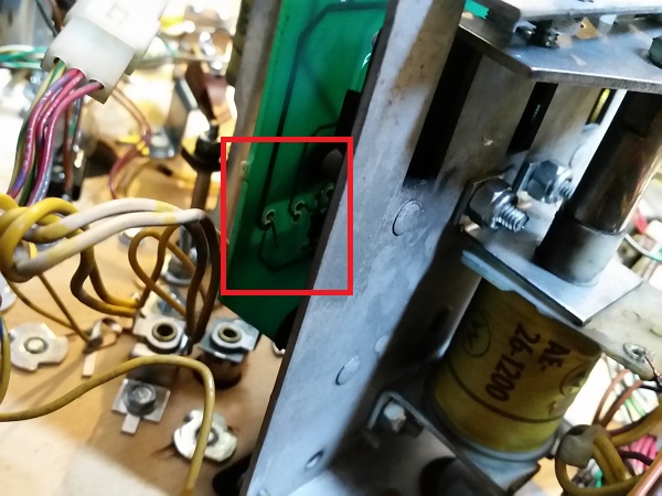
I don’t have any of these spare, so it’s been noted down for the next parts order I place. Fixing that switch issue will have to wait for when I service that drop target bank in a future update. But I had a quick look online and found the part required. Thankfully it can be purchased locally. So that leaves just the ramp switch to look at now. The assembly used to raise and lower the ramp contains 2 coils, a latch plate and a switch. A large coil pulls in a plunger, which raises the ramp. Because the ramp can be raised for an extended period of time, the coil only fires for a moment, allowing the ramp to rise and a small plate to lock in place, keeping the ramp up. The second coil is a small one, and simply releases the the latch plate when the ramp needs to lower. The microswitch attached to the assembly tells the game if the ramp is up or down.
As I mentioned earlier, the behavior I was seeing was the small coil firing repeatedly, releasing the latch plate, trying to lower the ramp. The game felt the ramp was not lowered, even though it visibly was. I also noted in game play that the ramp didn’t rise when it should have – presumably because it felt the ramp wasn’t down. A closer look at the assembly told me the story. The plunger has a small metal arm, which moves along the blade of the switch. This arm was sitting on the wrong side of the blade. When the arm is up like this – it should close the switch to tell the game the ramp is down. It will never close the switch in this position.
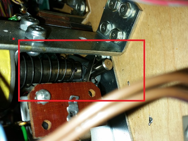
The only way I can see this happening, is someone in the past either removing the switch or pulling part of the assembly off and putting it back on incorrectly. It’s easy to fix though, I simply undid the two screws holding the microswitch to the assembly and got the arm onto the correct side of the switch blade. With the microswitch installed again – it was good to go.
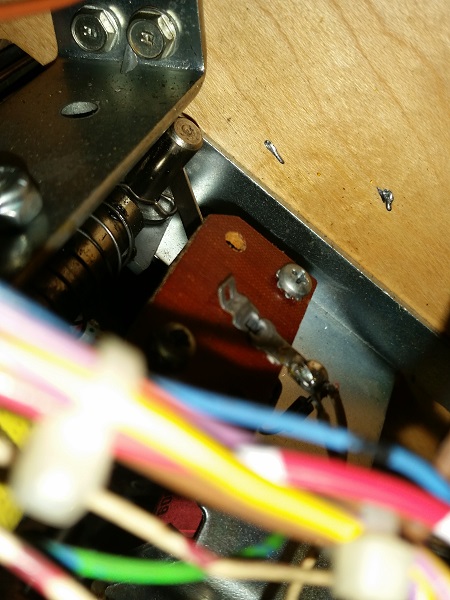
The game was fired up once more and the switch tested – now it was functioning correctly and the ramp raised and lowered as it should. I will be coming back to this assembly at a later time to completely strip and rebuild it. But at least for now it is working correctly.
Happy the switch issues (except for the drop target opto) were now resolved, I moved on to the solenoid test. I ran through each test and just like the switch test process, ticking off each solenoid that passed. In the end, I was left with 6 failures.
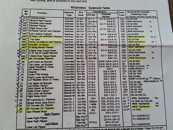
Five of the failures were flashers and caused by blown #906 bulbs. These were all replaced. It’s worth noting that in a number of cases, a flasher solenoid will trigger 2 or 3 flasher bulbs to fire, which is listed on another page in the manual. So it’s important to have the solenoid layout beside you while observing their behavior to make sure all flashers connected to a solenoid fire. I found a few cases where one of the #906 bulbs were fine, but the other 1 or 2 were faulty. The knocker failure was simply because it had been disconnected in the back box. I hooked it back up, tested it worked and then disconnected it again (i’ll leave it up to the owner if he wants it connected). It makes one hell of a noise and is the loudest one I’ve head to date (probably why it was disconnected!)
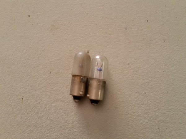
The next thing to look at is the GI in the back box and all cpu controlled lamps. The #44 lamps in the back box are quite filthy. All of them are still working though except for 2, which I replaced. The others were removed and cleaned up. By taking a few minutes to wipe the bulbs down, it helps improve the brightness.
While sorting out the back box lamps, I wanted to look at the lamps below the display. There are seven lamps which light features during game play, all were working except for one.
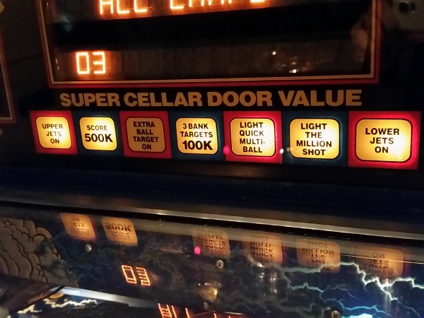
The lamps are attached to a thin pcb strip below the display, held in place by the #555 twist sockets. Each one was removed and cleaned and the faulty globe replaced.
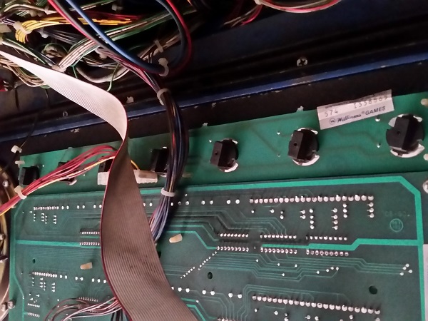
Testing again, all globes in the strip now worked correctly. Continuing on with the lamp test, my attention turned to the playfield. I ticked off the lamps that worked, leaving me with a list of non working cpu controlled lamps to investigate. I’ll sort the faulty GI lamps out when I go through the playfield assemblies later.
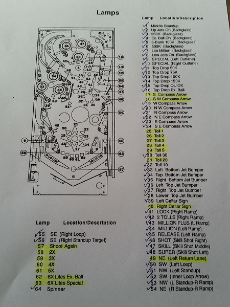
There were a couple of blown #44 lamps under playfield inserts and these were replaced. Next, I wanted to look at the bonus multiplier inserts. None of these were working. They all attach to a small PCB with the twist sockets.
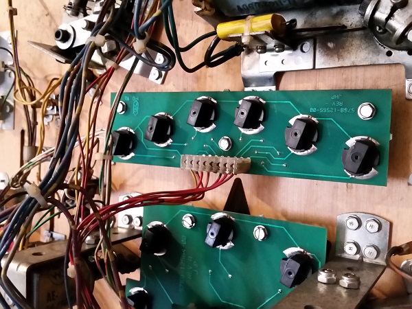
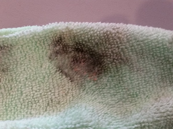
The plug was disconnected and the board removed. The underside of it is filthy.
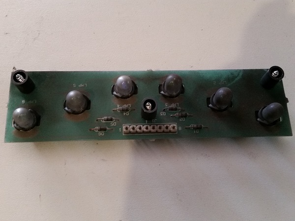
The board and lamps were cleaned up, making it look a lot better. While cleaning them I inspected each bulb and found that only 2 of them were blown, both of which were replaced.
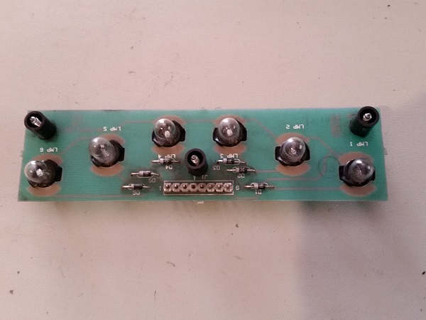
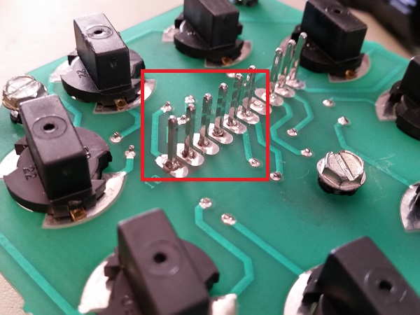
The two blown bulbs didn’t explain why none of the bulbs worked in lamp test mode though. Looking at the connector pins, I could see the cause – some cracked solder joints.
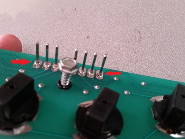
I reflowed fresh solder across the pins and then wiped down the underside of the inserts. Quite a bit of dirt came off the insets. Removing this should help brighten them up during play.
The game was switched on and now all eight multiplier lamps came on during the lamp test. Excellent – let’s keep going! The next set of lamps to look at are the skyway tolls. These too sit on a small PCB using the twist sockets. There are 8 lamps in total and currently only 2 of them are working. The PCB was removed from the machine, it too is filthy.
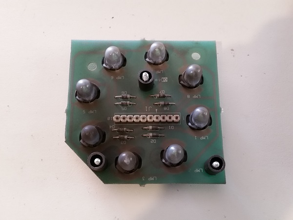
The board and globes were wiped down to clean them up. Again the globes were inspected, but all were fine and none needed to be replaced. So why did only 2 work?
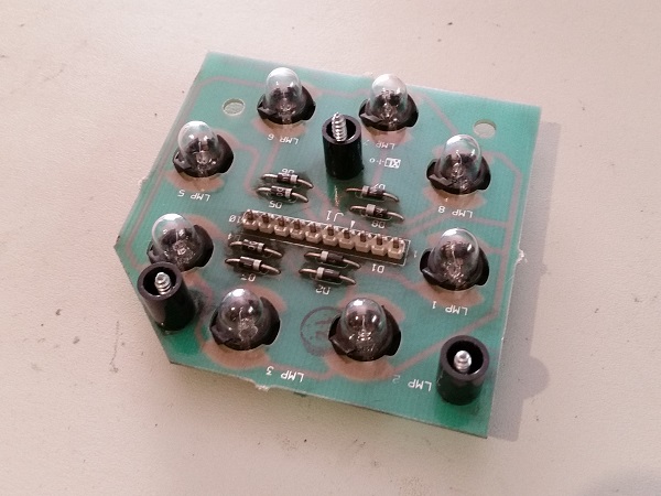
Cracked solder joints were again the cause here. This time, I could actually wiggle the pins with my finger. Fresh solder was applied to the connector pins and the board installed back into the machine. Again into test mode I went and now all 8 lamps worked correctly.
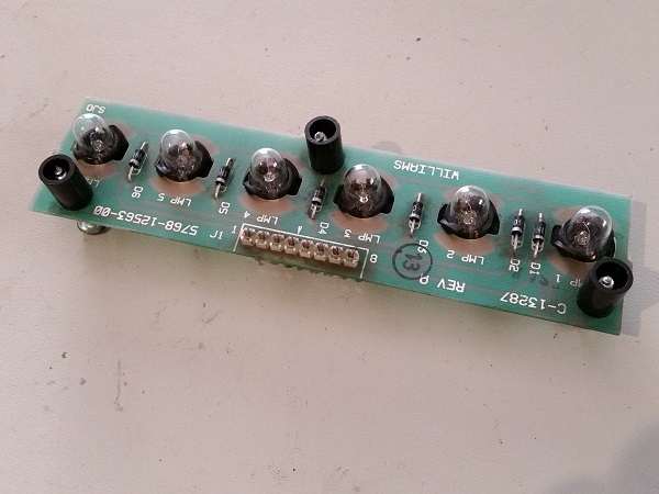
Because I had found cracked solder joints two of the lamp boards, I wanted to look at the other three in the machine. Next up was a strip of lamps that lead to the single drop target. All of these lamps were working, but obviously the board and bulbs could do with a clean.
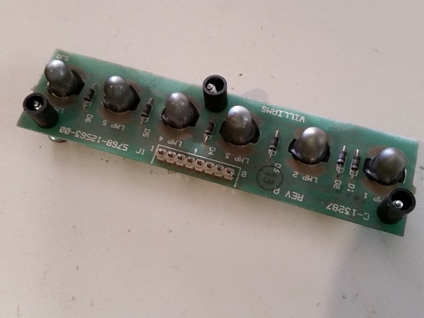
The board and lamps were cleaned up and the connector pins checked. No broken solder joints on this one thankfully. I reflowed fresh solder on to them anyway since I had the board out.
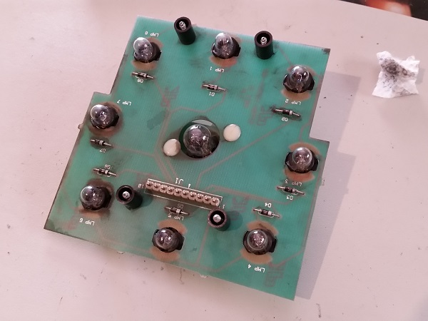
The next lamp board to look at is the one that sits below the large compass on the playfield. I had already replaced the #906 flasher earlier as it was one of the solenoids that initially failed. The rest of the board was quite dirty though, just like the others.
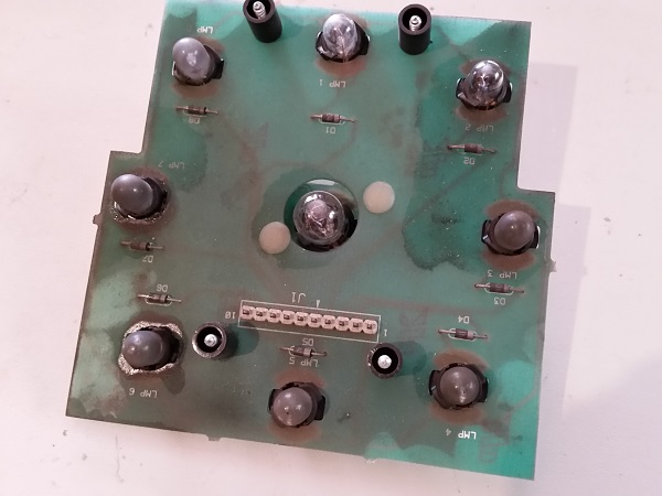
It was given the same treatment and cleaned up, along with the bulbs. No broken solder joints here either, but again fresh solder was added.
The last lamp board to look at sits all the way at the back of the playfield. It has the long storm plastic sitting in front of it and is removed as a unit. While I had this out I need to look at 3 of the #906 flashers which were not working during the solenoid tests.
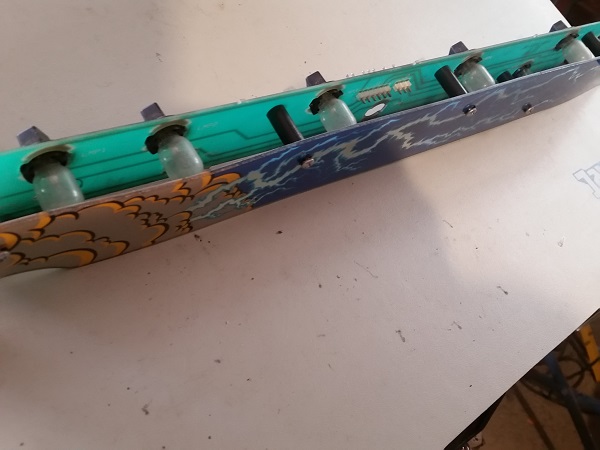
This one isn’t too dirty, but the bulbs can certainly be cleaned up to help improve their brightness. I also noticed that one of the twist sockets for the GI lamps were missing. I have some spares for these so can easily replace it.
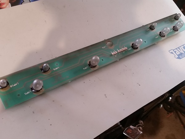
The plastic was removed from the board and then cleaned. I also polished it up with some Novus. The rear of the plastic had been quite dirty, but now it’s nice and clean, so should light up great with the GI and flashers.
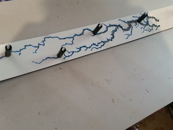
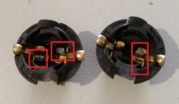
The #906 bulbs which were failing in the solenoid test were due to corrosion in the twist sockets. I had some spare ones of these luckily and was able to swap them out. With the missing GI lamp replaced and the faulty sockets gone, I put them game into test mode again and checked the flashers triggered correctly in the solenoid test. All was good.
The last faulty cpu lamp to look at sits above the right cellar scoop (the one with the yellow condom covering it). The lamp itself looked fine and on closer inspection the issue was a wire had come loose from the socket. No doubt about it, that would put a serious road block in the path of the lamp working. Poor angle for the photo, but basically the red wire was away from the socket lug and hanging freely below.
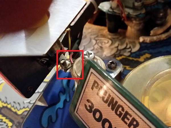
The soldering iron came out again and the wire connected back up. Now all the CPU lamps were sorted out and I could tick this off my to do list. The playfield was looking much brighter as a result. I’d -REALLY- love to LED this machine out, but the owner doesn’t want to (which is fine – it’s his call). I still need to wipe clean some of the bulbs under the playfield, which should help make it even brighter, but i’ll do this as I work my way through the machine assemblies.
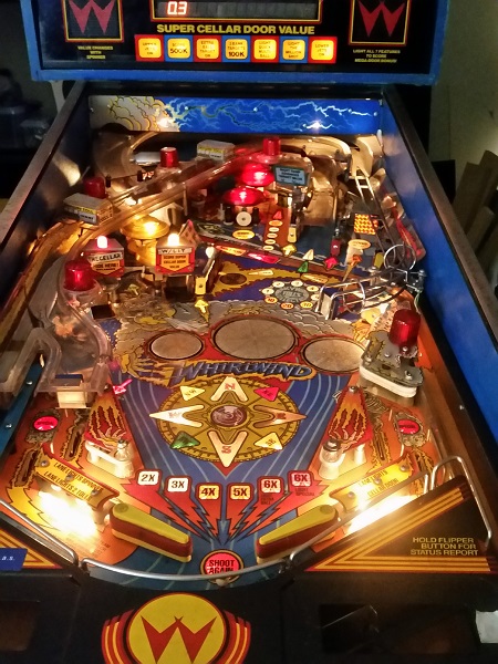
There isn’t much more I can do right now until parts arrive. I’m happy with the results of the switch, solenoid and lamp tests. The drop target opto issue I’ll get to at a later time as with the handful of faulty GI lamps tucked away under plastics and ramps. The main bits I’m waiting on at the moment are coil sleeves and two flipper rebuild kits and I expect them here tomorrow. The flippers are weak on this machine (especially the lower right flipper), so will be transformed once rebuilt. My next update is planned to cover the apron area, so i’ll be rebuilding the out hole kicker, ball serve, trough, bottom kick back and possibly the sling shots. If I can squeeze them in, i’ll also rebuild the shooter rod and lower flippers – so it could be a monster sized update. There is quite a bit to work on with the machine, so I expect to be busy for awhile yet. Thankfully, I really enjoy this stuff 🙂
