It’s time to finish off my Fireball Classic restoration. When I started my Xmas / New Year holidays, I had the goal of finishing this off before I went back to work. Looks like I’ll get there with a day to spare. With the presentation of the machine completed in my last update, I wanted to address the last few operational issues with the machine. The first thing to look at is the MPU board. As mentioned a few times in earlier updates, the MPU board has suffered from corrosion. A battery left in way too long managed to spread damage all around the outer edges on three sides of the board and it had begun to work its way in at the components. Damage was also done to the J4 pins and even the female connector pins on this plug.
I was able to obtain a second hand original Bally MPU board in excellent condition with no corrosion damage at all. The male pins at J1, J2, J3 and J4 were all replaced, along with new 5101 RAM and a lithium battery to ensure there is no risk of battery damage in the future. This one came from a Baby Pacman machine I’m told. New game ROMs were also burned and installed.
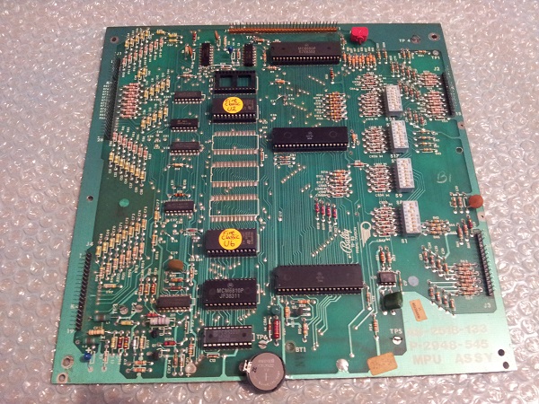
I’m very happy to be installing this into the machine. One day I will sell the game and I’d hate to sell it with a dodgy MPU board. This actually gives me a great opportunity to try my hand at restoring the board to repair the corrosion damage without taking the game offline. If (..when) I get around to this i’ll certainly make a post about it and detail the work I do on it.
I removed the old MPU board and noticed some corrosion had spread to the two metal frames which the board attaches to.
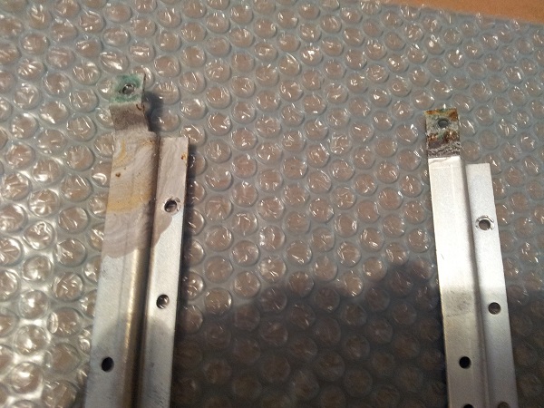
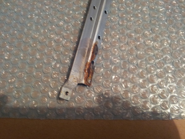
I got out some steel wool and went to town on scraping it all off. I then used some vinegar to neutralise and prevent any further damage. I’m not sure on the best practices with this sort of thing but I’d hate to see corrosion transferred to the new board.
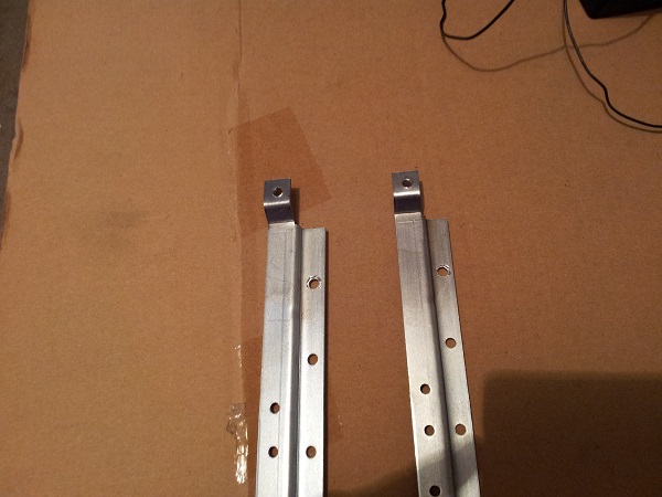
While I was at it, I replaced the two metal screws which attach the board to the frame. Again, I’m playing it safe and want to minimise any chance of the corrosion be transferred.
With the new board installed, I had a close look at the 4 connectors to see which ones needed to be repinned. J1, J2 and J3 were all fine. There is no sign of corrosion on any of the pins. Looking closely at the old MPU board I can see corrosion damage in the area of those connectors, but it had not reached the actual pins yet. J4 on the other hand was a different story.
It was originally an IDC style plug, but I was unable to source any 0.100″ connectors. J4 was promptly repinned with a new pins and connector. Having a closer look at the connector I could see some darker pins and corrosion on a number of them.
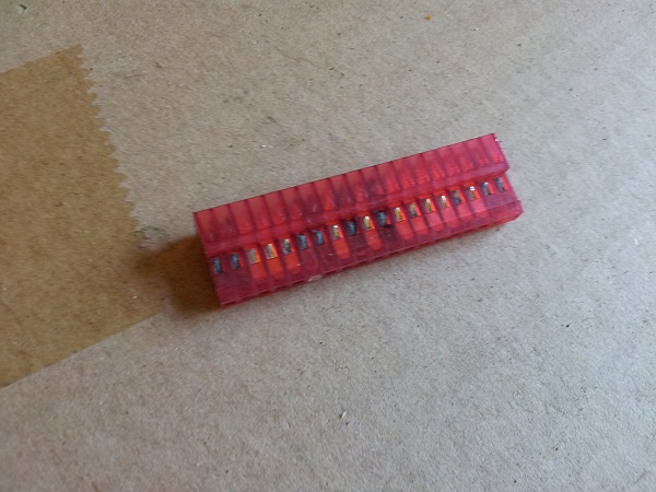
When I purchased the new connector, I also purchased a bulk lot of 100 pins. I hadn’t crimped this style of pin before and want to have a few practice attempts first. This proved a wise move. My first few attempts weren’t the best, but I finally got the knack for it. Each wire was cut, new end stripped and then crimped to a new connector and installed into the new plug. It was slow going at first, but I got there. I also salvaged a small key pin from an old harness so I could correctly mark the connectors key.
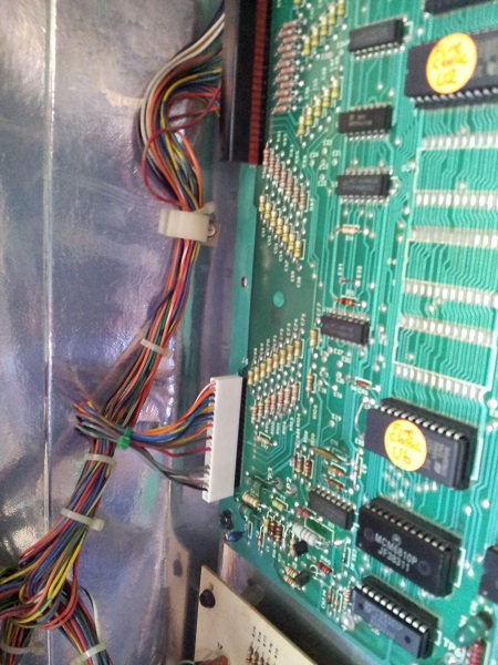
Next on my hit list was the broken IDC plug on the solenoid driver board. This is the one I mentioned in my last update where pin 10 had been bent and the wire soldered directly to it. The connector was then in 2 pieces. Thankfully the machine had still worked. By this stage I had got a rhythm together for the crimping of the pins, so this turned out to be much quicker than I had expected. I also took the time to remove the old male pin connector and replace it with a new one. Since pin 10 had burnt out at some point in the past and it was now weakened from being bent, it seemed like a wise move. With both the connector and pins redone, I was happy.
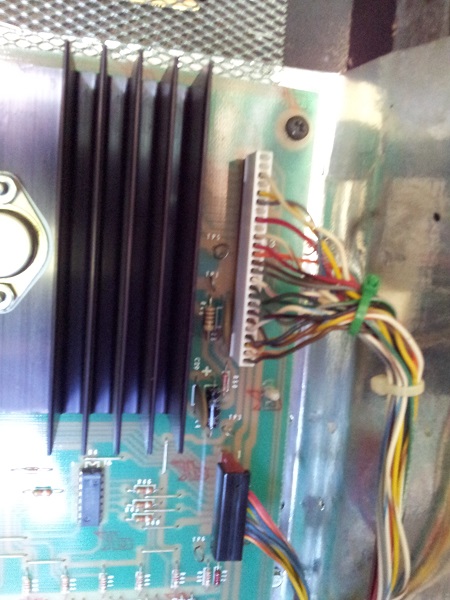
With the new board installed and two connectors repinned, it was time to give the new board a proper test. After a few games I noticed that the ghosting was almost non existent. I suspect now I just need to tune those switches a bit.
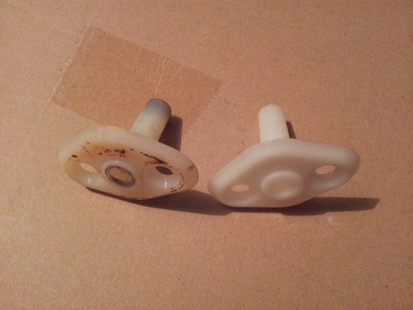
Something I had wanted to do awhile back was replace the shooter bushing. At the time there was only 1 place overseas with the part and with shipping factored in for the single piece, it wasn’t worth it. I recently found Marcospec now had them in stock and I included one in my recent order. Installing it was a 2 minute job and the shooter rod now feels better than ever when using.
A small issue that’s hung around for awhile is a problem with the 20K and 150K bonus lamps not working correctly. I suspected it was a connection issue as the globes are fine and after I reseat them, they work for a few games and then go out again. With the machine off, I pulled the playfield up and took a much closer look at the sockets themselves. The lamp connectors looked fine and showed no reason not to be making good contact with the bulb. The wires were soldered firmly to the socket. I decided to look at the lamp driver board next and test the transistors. I found two transistors with issues Q18 and Q19. Both of these had corrosion on the legs. Q19 had corrosion on all 3 legs, while Q18 only had it on 1 leg.
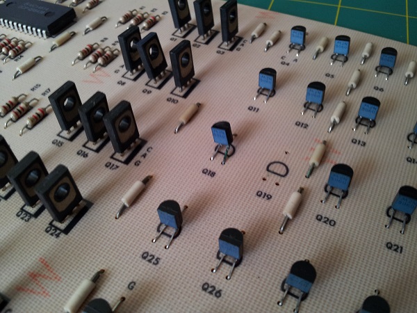
Both were removed and replaced with new transistors. The board was installed again and the machine fired up to test the two lamps. They still wouldn’t light. I didn’t check if Q18 and Q19 were related to these two lamps, I had just assumed since I had found two not working and I had two bad lamps – but they were worth replacing anyway, so it wasn’t time wasted. Again I pulled the playfield up with the game off and had a look at the sockets. It then occurred to me to check the ground wire that runs between each socket. I found that on the 20K bonus lamp, the blob of solder was not actually connected to the socket. In fact I could move my screwdriver below it and move the whole thing around.
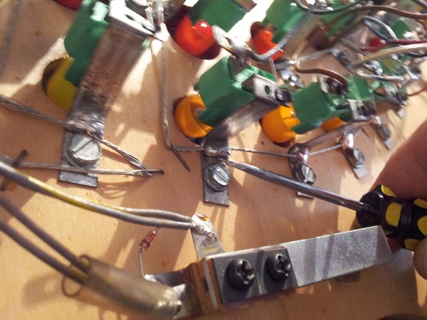
I then checked the 150K bonus lamp and noticed this one was not soldered at all. I resoldered the wire to the lamp socket and fired the machine up. Finally! Both 20K and 150K lamps were now lighting. After several games they remained lit. Because the solder on a number of the sockets is positioned in the bend where the socket can be bent back for removing the globe, it came loose on both (and fell off in 1 case). Another thing off my to do list.
That just leaves me with one last issue to sort out. The highscore feature lamp in the backbox. This lamp should light up when in attract mode and the game shows the current highscore. It lights up “Highscore” on the backglass. Right now, that does not happen. When I start a new game, this lamp flashes on 3 times and that’s it. So that tells me the globe is fine and the wire running to it is fine, but it doesn’t light when it’s supposed to.
Opening up the door, I can see a hacky looking wire (colour code red/white) that runs from the “game over” globe to somewhere else. You will also note that there is a disconnected white and gray wire. Something tells me this should be connected somewhere.
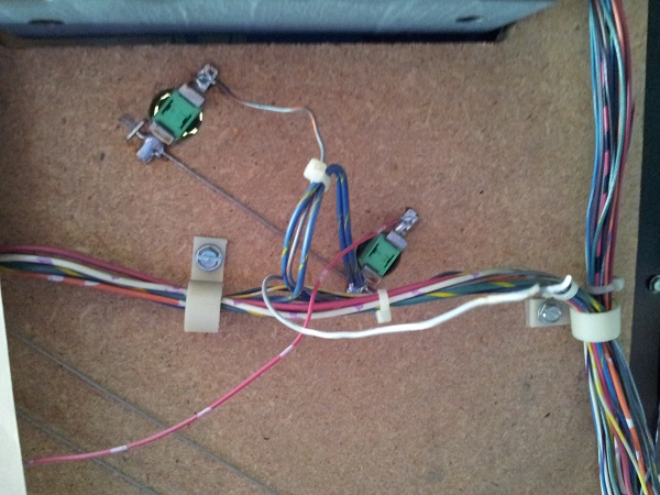
Looking at the manual, the “game over” wire is colour coded white and gray. OK, so this is another issue on top of the Highscore lamp. The red and white wire is not listed in the manual, so this shouldn’t be here. The “Game over” lamp does work – I’ve seen it when the game completes and it only lights when it’s supposed to. What’s the red/white wire running to? The “match” lamp.
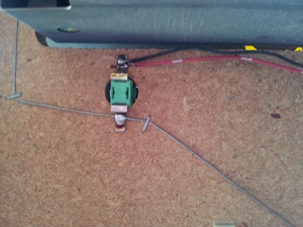
The match lamp also has a black and blue wire running to it. Looking again at the manual, this is the correct wire code for match. So I’d say, the game over lamp was not working at some point and instead of fixing the issue it was connected to the Match lamp so it would light when Match lights. This is OK I guess so long as the match feature is enabled. If that’s disabled, Match won’t light at the end of the game and “Game Over” won’t light. I’ll remove that red and white wire now and i’ll also hook up the white and gray wire to “Game Over” like it should be.
I fired the game up and went into test mode, as I expected “Game Over” no longer lights. The wires from the lamps are connected to the lamp driver board via a molex connector.
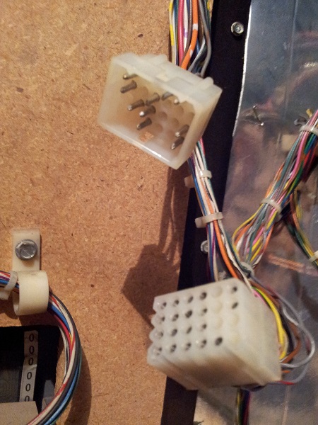
I decided to do a continuity check. Firstly from the lamp tab each wire is connected at to the male molex pin. This was successful for all lamps (Ball in play, Game Over, Highscore, Match, Tilt). I then did another continuity from the female pin to the IDC connector on the lamp driver board. Again, all OK. I connected the molex plug back up and then did a final continuity from the lamp tab with wire to the IDC pin. This worked for all of them except “Game Over” and “HighScore”.
That’s interesting. Something about the molex connector. I had a look at the pins and they looked fine. Then it dawned on me that the male pins for “Highscore” and “Game Over” did not match up with the female pins for these wires. They were both running to different pins on the Lamp Driver board! Both pins are not marked as anything in the manual, although it’s interesting that the pin “highscore” was connected to flashes 3 times at the start of a new game. Possibly a feature used in other Bally games but not in FBC?
Anyway, the two male pins were removed from the plug and put into their correct positions. I fired the game up and immediatly noticed that “Game Over” was now lit when the game first boots. This had not been happening before. I waited for the current highscore to display and when it did, the “Highscore” lamp now lit up. It then went off when the highscore was hidden. I played a few games and tested each of the lamps out. Everything was now working correctly. So in summary, two pins were incorrectly placed in the molex connector and some hacky wiring done on top of it instead of fixing the issue (which only fixed it partially anyway).
So that’s it. All the problems were now sorted out. With that out the way, it was time to move the Fireball Classic from it’s temporary position in the middle of the garage and officially add it to my line up.
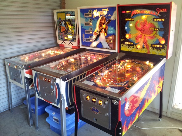
Working on this machine has been an incredible amount of fun. It took me out of the comfort zone I had developed while working on my Nugent and had me deal with many new issues to expand my experience and knowledge. It’s a really nice looking game and I’m happy to have it in my line up.
