The first two weeks of owning the Pole Position II machine was mostly spent playing it 🙂 It’s been a lot of fun and the kids (especially my son) are enjoying it.
As I mentioned in the previous post, there are a lot of little things that need attention on the machine. Nothing critical – the game plays fine – but can be given a huge visual boost with some attention. What I needed to do first was some research on pole position machines and find a starting point.
I spent a few nights hitting Google with a lot of search queries to find out all I could about the machine. The one I have is the Namco version and not as common as the Atari version – making artwork sourcing much more difficult (if not impossible). I was able to track down photos taken of similar machines at Aussie Arcade (where I hang out a lot) and a second link with some excellent photos taken from several angles (here).
With the images downloaded, I had them printed out and put them into my research notebook. On my previous projects I’ve made a point of keeping notes and research together in a printed format that I can access while in the garage working. It’s handy to have the information within arms reach, and also reference to spot smaller details that don’t always jump out the first time you see the photos.
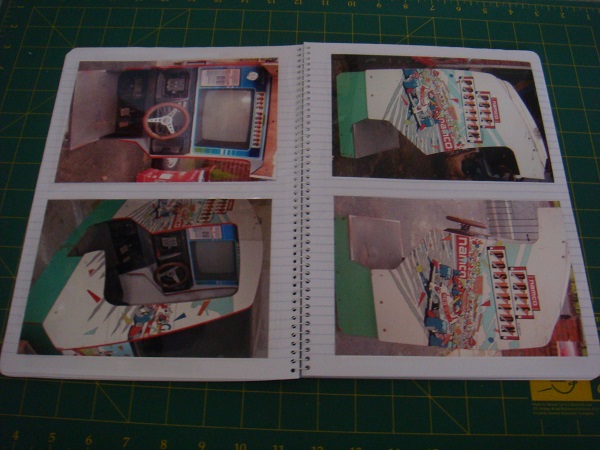
After some research, I decided on three things I give some initial attention to. These are:
1) Restore black metal brackets (3 of them)
2) Replace black screen bezel & adjust screen settings
3) Replace screen acrylic and have artwork printed for it
All of these can be done in parallel and still leave the machine operation for continued play during the week 🙂 I’m going to focus on point #2 in this post. I will go into more detail about the other two over the coming weeks.
The black screen bezel is in a bit of a sorry state. A large rip in the left side was not good, and the other sides looked like they had seen better days. It appeared a little uneven also as I could see the very edges on one side of the monitor (where the bezel should have been covering).
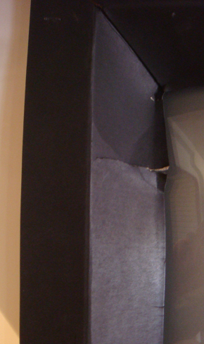
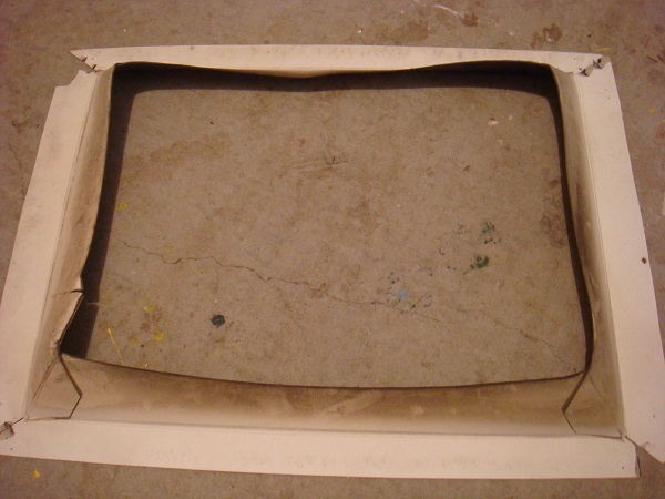
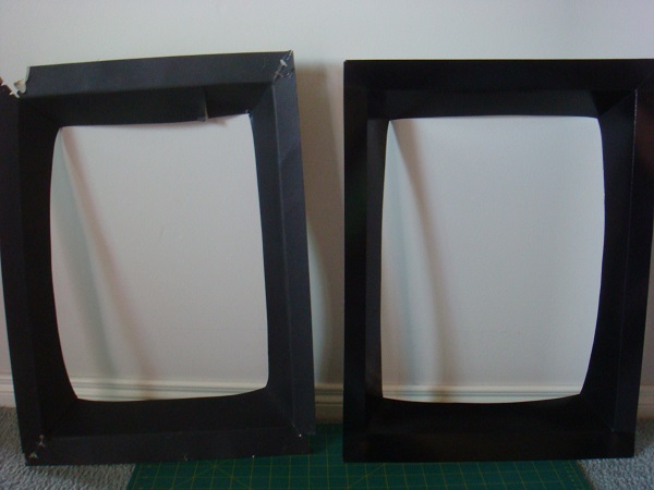
I had already removed the acrylic to start working towards replacing it, so proceeded to remove the existing bezel. I did it as carefully as possible to retain it and use as a template for constructing a new one. The existing bezel is made out of some thick cardboard. Here it is removed – and it’s certainly seen better days. The “wavey” sides explain the uneven sit when it was attached.
I went and purchased some thick cardboard from an art store to use as a replacement. I also purchased some thinner (cheaper) white cardboard to use as a template (aka practice run). When happy with the template, I could then transfer that to the more expensive black cardboard and know it’s going to fit right.
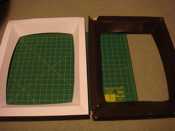
The template took about an hour to put together. I used the same construction method as the existing bezel, keeping the measurements the same.
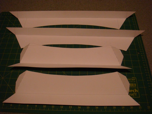
Using sticky tape, I put the template together and adjusted until it sat correctly. Here is the template side by side with the original.
Happy the template was going to work, I transferred it to the better quality card and assembled.
While I was looking at the bezel, I figured I would also deal with a few issues around the monitor. I found that when fitting the new bezel it just wouldn’t sit right. After adjusting it a few times it dawned on my that maybe the monitor was actually not sitting correctly. I placed the original bezel back on and sure enough, it only sat in place because it had a tear on the left side and the other edges being worn. The monitor was about 10mm too far forward and also 15mm too far to the left. It also needed to sit about 5mm higher. Very minor adjustments, but enough to make a differences. This explained why my new bezel wouldn’t fit and cover the correct areas.
I love the flip top design on the cockpit – makes easy access to the monitor:
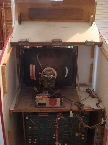
I removed 3 screws holding the monitor panel in place and then adjusted until it was in the correct position and the bezel sat nicely.
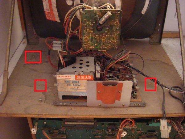
One final thing to sort out with the display – the horizontal and vertical position. The current image was slightly too high and to the left. Since the back of the cockpit was already opened to move the monitor, I took the opportunity to adjust the dials and fix the video position. I started by marking the current position of the two dials with a sharpie so I could always undo any changes. After a few adjustments and checking the new position, I was happy with the video position. I also removed additional screws and bits of unused wire that had been left over from previous work.
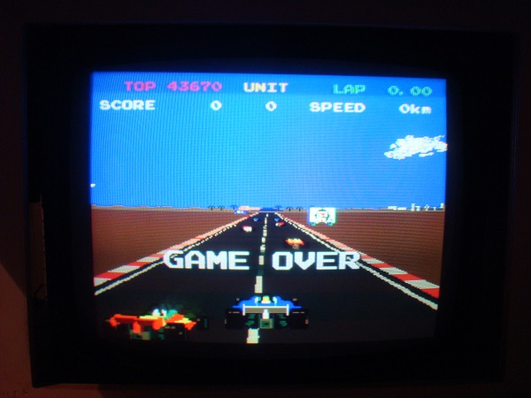
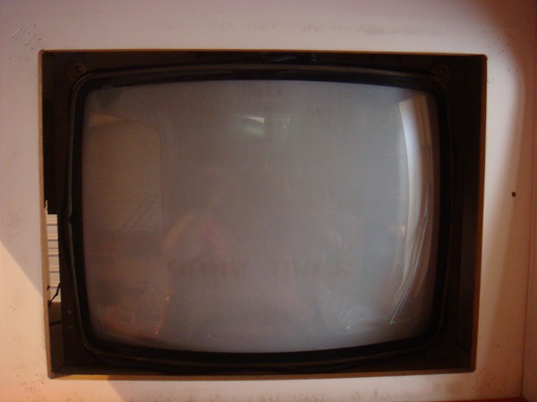
With the monitor position fixed and secured – it was time to complete the bezel and get it into the machine.
Here is the old and new side by side:
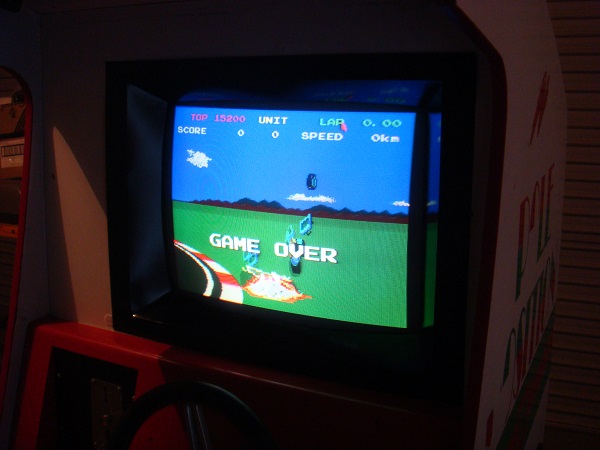
And the new one installed:
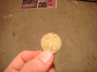
To round this update off – while digging around in the back of the machine, something caught my eye. Tucked away in the corner, an old $1 coin that was covered under a mountain of dust. It would be nice to discover a few more of these hiding inside as I restore the machine 🙂

Fantastic Job — do you have the templates in digital format? I’m having to create one for my Tempest, but I don’t have the orginal to work from.
No sorry – the bezel was created by hand off the original and I never went to the trouble of converting it into a reusable digital format.